Integral ankle support for a shoe

a technology of ankle support and shoe, which is applied in the direction of bootlegs, stiffeners, uppers, etc., can solve the problems of callouses on the foot and ankle, requiring frequent readjustment, etc., and achieves the effects of increasing the performance capability of the wearer, increasing the tensile strength of the ligaments in the wearer's ankle, and increasing the stability of the foo

Active Publication Date: 2012-08-21
ECHOLS TONY RYAN
View PDF17 Cites 18 Cited by
  • Summary
  • Abstract
  • Description
  • Claims
  • Application Information

AI Technical Summary

Benefits of technology

[0008]In general, the ankle support, which is located out of sight within the walls of the shoe, includes a support element and a cushioning element. The support element is structurally strong yet partially flexible, and is configured to prevent lateral and medial rolling of the ankle. The support element is constructed of lightweight plastic that while in general is rigid enough to provide the requisite degree of ankle support, but is still flexible enough at body temperature to be moldable to the shape of the wearer's foot. The cushioning element provides both comfort to the ankle portion of the wearer's foot, and additional ankle support. The ankle support is an integral and permanent part of the shoe structure, with both the shoe and the ankle support assembled together.
[0029]Another object of this invention to be specifically enumerated herein is to provide an ankle support in accordance with the preceding objects that will conform to conventional forms of manufacture, be of relatively simple construction and easy to use so as to provide a support that will be economically feasible, long lasting, durable in service, relatively trouble free in operation, and a general improvement in the art.

Problems solved by technology

A possible drawback associated with such removable inserts is that the device may separate from the thistle-type fastening strips during wear and shift within the shoe, thus requiring frequent readjustment.
The shifting of the removable insert may also create friction that might lead to callouses on the foot and ankle.

Method used


Image

  • Integral ankle support for a shoe
  • Integral ankle support for a shoe
  • Integral ankle support for a shoe

Examples


Embodiment Construction

[0041]Although preferred embodiments of the invention are explained in detail, it is to be understood that other embodiments are possible. Accordingly, it is not intended that the invention is to be limited in its scope to the details of constructions, and arrangement of components set forth in the following description or illustrated in the drawings. The invention is capable of other embodiments and of being practiced or carried out in various ways. Also, in describing the preferred embodiments, specific terminology will be resorted to for the sake of clarity. It is to be understood that each specific term includes all technical equivalents that operate in a similar manner to accomplish a similar purpose. Where possible, components of the drawings that are alike are identified by the same reference numbers.

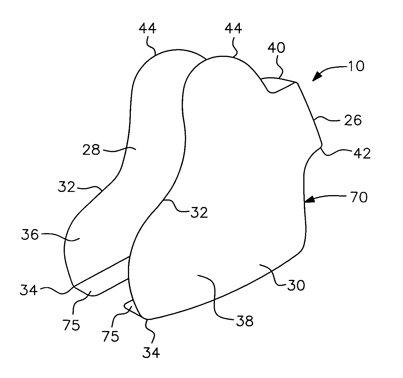
[0042]Referring now specifically to FIG. 1 of the drawings, an ankle support in accordance with a first embodiment of the present invention is generally designated by reference n...


PUM


Abstract

An integral ankle support for a shoe has a support element and a cushioning element. The support element has horizontally elongated, generally parallel, and panel-like edge upstanding wings having corresponding front and rear ends joined at their rear ends by an integral, curved, and edge upstanding bight panel portion. The support element is constructed of semi-rigid, but partially flexible, material that is lightweight and moldable. The support element has a bottom tab that is oriented substantially perpendicular to the wings and that extends inwardly under the insole of the shoe. The ankle cushioning element is located on the inner surfaces of the rear ends of the wings and the central portion of the lower margin of the bight panel portion. The ankle support is incorporated as part of the internal structure of the shoe so as to remain fixed in place and provide enhanced support to the wearer's foot.

Description

BACKGROUND OF THE INVENTION[0001]1. Field of the Invention[0002]The present invention generally relates to an ankle support that is an integral part of a shoe. More specifically, the present invention relates to an ankle support that is an internal and integral component of the shoe, is flexible enough to mold to the shape of the wearer's foot, and yet rigid enough to provide enhanced support to the ankle portion of the wearer's foot.[0003]2. Description of the Prior Art[0004]Various forms of ankle and interior shoe bracing devices are known. Examples of these previously known devices are disclosed in U.S. Pat. Nos. 3,237,319, 3,834,377, 4,385,456, 4,821,743, and 5,175,947.[0005]An insertable athletic shoe insert is described in the present inventor's U.S. Pat. No. 5,449,005. The insert is attached to the ankle and heel portion of the interior of the shoe by thistle-type fastening strips. A possible drawback associated with such removable inserts is that the device may separate from...

Claims


Application Information

Patent Timeline
Patent Type & Authority Patents(United States)
IPC IPC(8): A43B7/20
CPCA43B7/20A43B23/0285
Inventor ECHOLS, TONY RYAN
Owner ECHOLS TONY RYAN
Why Eureka
Try Eureka