
Dial indicator display device

a display device and dial indicator technology, applied in the direction of identification means, instruments, horology, etc., can solve the problems of reducing readability, increasing power consumption, and difficulty in reading the indicated value when a hand is positioned between two numbers, so as to improve the readability of values

Inactive Publication Date: 2011-05-10
138 EAST LCD ADVANCEMENTS LTD
View PDF11 Cites 14 Cited by
  • Summary
  • Abstract
  • Description
  • Claims
  • Application Information

AI Technical Summary

Benefits of technology

[0010]A first object of the invention is therefore to provide a dial indicator display device that improves the readability of values indicated by the hands.
[0011]A second object of the invention is to provide a dial indicator display device that improves the readability of both the values indicated by the hands and the information displayed on the display panel when information is displayed on the display panel.
[0012]A third object of the invention is to provide a dial indicator display device that improves the readability of both the values indicated by the hands and the information displayed on the display panel when the hands include an hour hand, a minute hand, and a second hand.

Problems solved by technology

A problem common to the timepiece taught in JP-A-2006-242717 and conventional analog timepieces is that while the numbers shown on the dial are used to read to value indicated by the hour hand and minute hand, reading the indicated value when a hand is positioned between two numbers is more difficult.
This loss of readability is particularly a problem with measuring instruments and meters that require accurately reading the indicated value.
If a second hand is added the display position of the auxiliary information must be moved frequently, thus reducing readability and increasing power consumption as a result of frequently changing the display.
If this information display device is used in a wristwatch or other battery-powered device, increased power consumption creates the problem of a shorter battery life.

Method used


Image

  • Dial indicator display device
  • Dial indicator display device
  • Dial indicator display device

Examples


embodiment 1

[0109]Arrangement of a Combination Timepiece

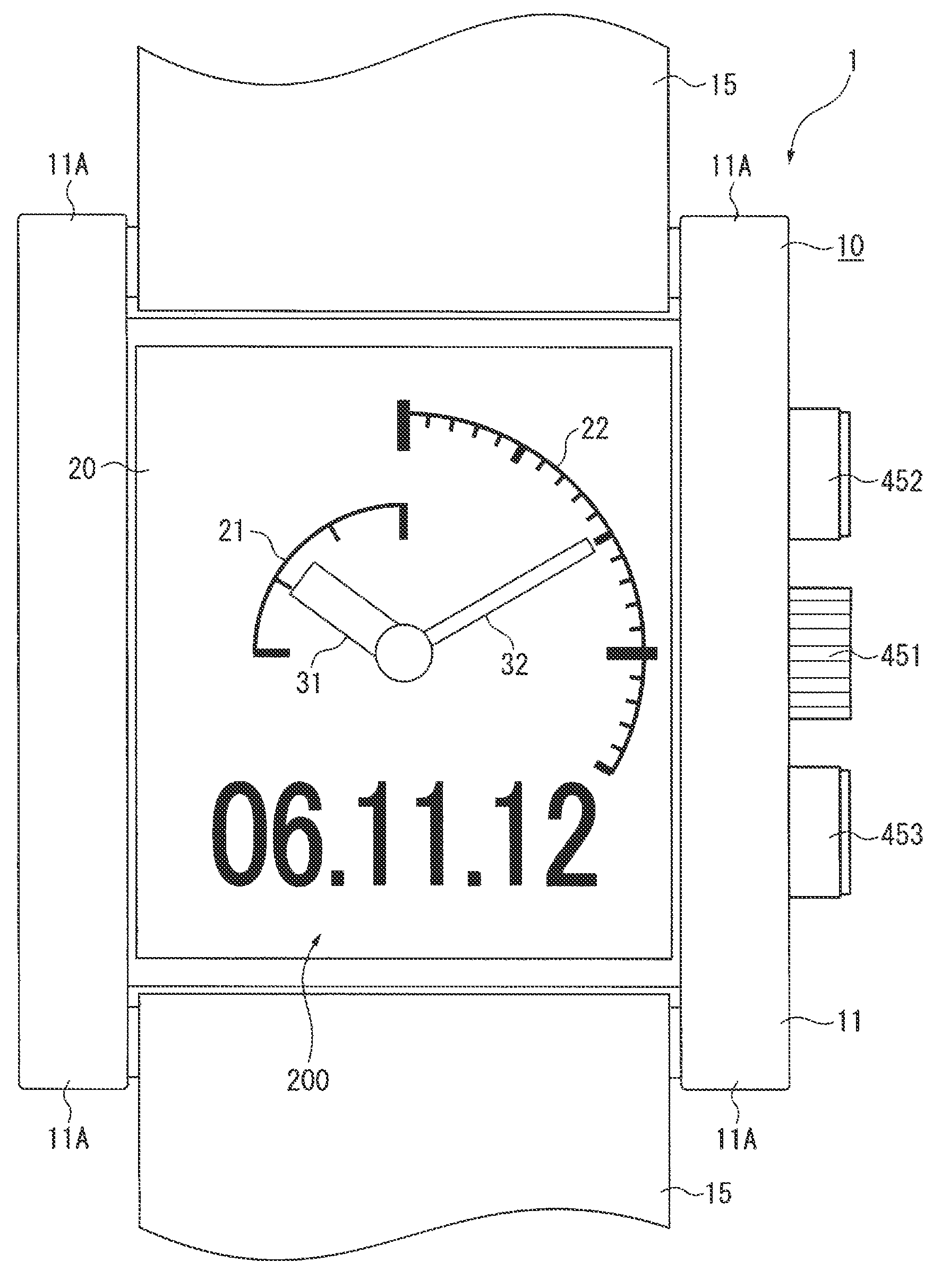
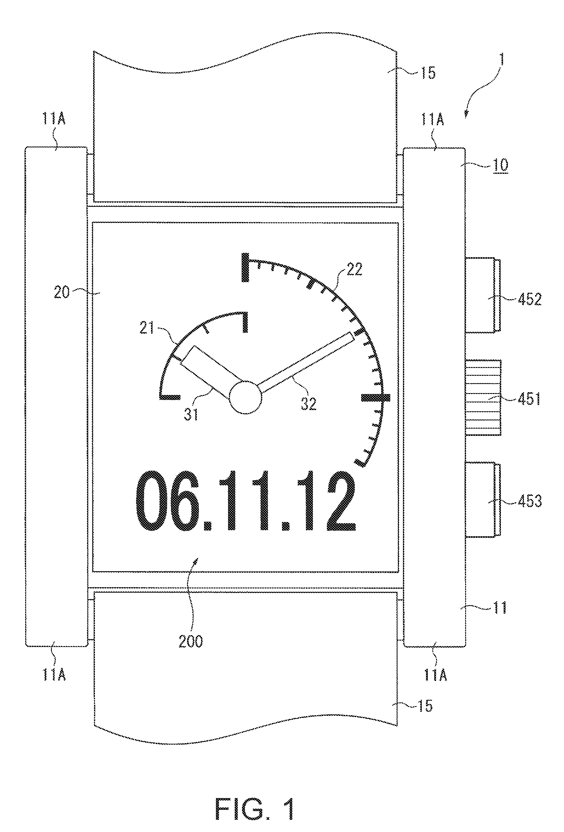
[0110]FIG. 1 is a view from the front of a combination timepiece 1 rendering using the dial indicator display device according to the present invention.

[0111]This combination timepiece 1 has a timepiece body 10 and a 15, and is rendered as a wristwatch that is typically worn by the user on the wrist.

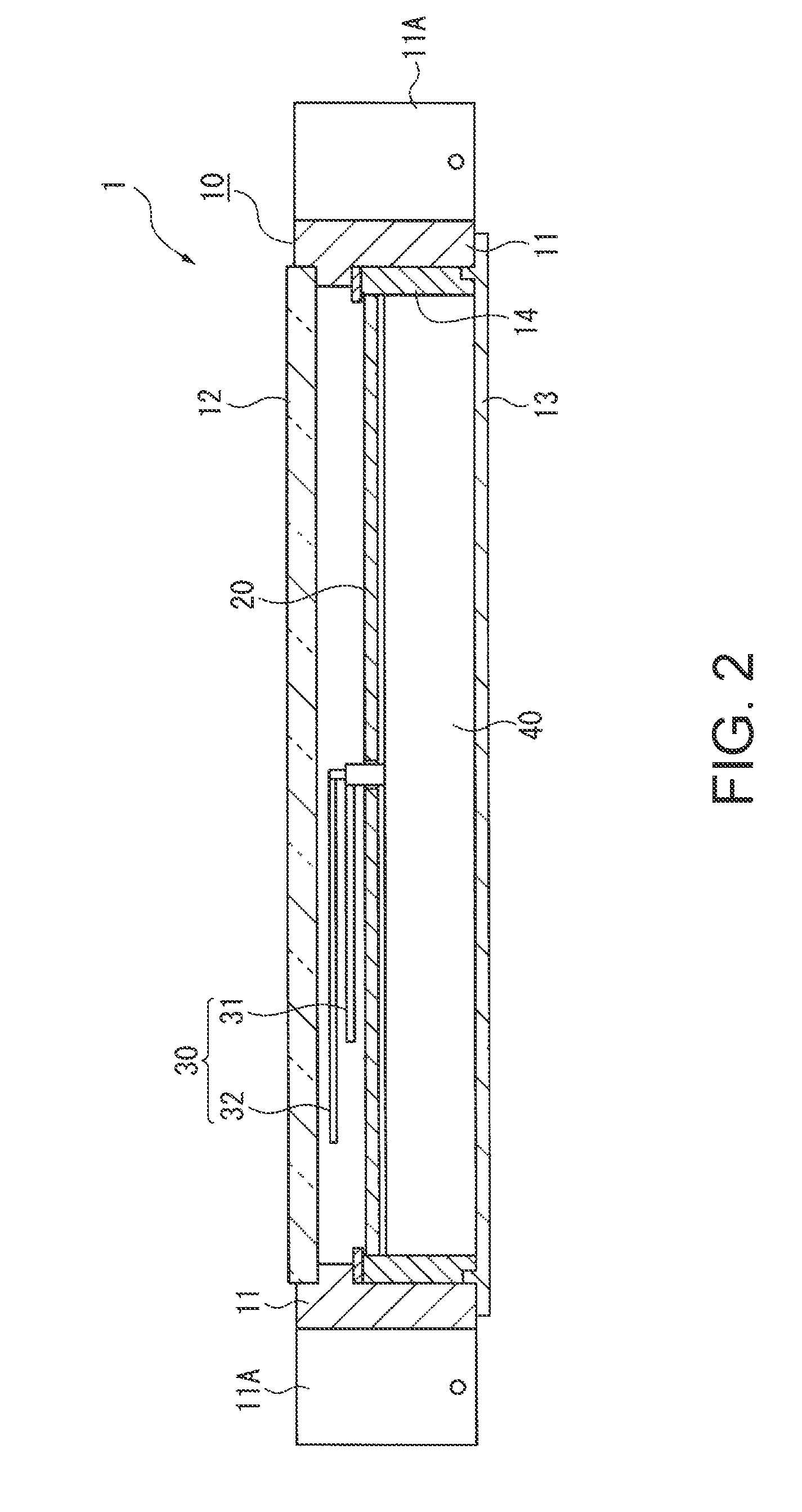
[0112]As shown in FIG. 2, the timepiece body 10 has a case member 11 (body) that is a rectangular tube in shape, a crystal 12 that covers the front side of the case member 11, and a back cover 13 that is removably affixed to the back of the case member 11.

[0113]The case member 11 is not limited to a rectangular cylinder shape (that is, rectangular in plan view), and the invention is not limited to the shapes shown in the figures and the case member 11 may be a round cylinder (circular or elliptical in plan view), for example.

[0114]A pair of lugs 11A for attaching a wristband is disposed at each of the opposite ends of the case member 11, and sp...

embodiment 2

[0173]A second embodiment of the invention is described next. Note that in the embodiments described below identical or similar elements are identified by the same reference numerals, and further description thereof is omitted or simplified.

[0174]As shown in FIG. 6, a combination timepiece 1B according to a second embodiment of the invention differs from the combination timepiece 1 of the first embodiment in that a second hand 33 is added and a scale 27 for the second hand 33 is displayed on the display panel 20, but other aspects of this embodiment are substantially the same as described above. This combination timepiece 1B is thus a timepiece that indicates the hour, minute, and second using corresponding hands.

[0175]As in a conventional timepiece, the second hand 33 is attached to and driven by a specific wheel in the wheel train 47.

[0176]However, while the second hand is normally longer than the hour hand and minute hand in a conventional timepiece, the second hand 33 in this em...

embodiment 3

[0184]A third embodiment of the invention is described next.

[0185]The combination timepiece 1C according to this third embodiment of the invention disposes the rotating axes of the hour hand 31 and minute hand 32 at different positions separated on the plane of the display panel 20 instead of coaxially as in the embodiments described above.

[0186]More specifically, the hour hand 31 is located in the top left part and the minute hand 32 is located in the bottom right part of the display panel 20.

[0187]The scale display control means 414A therefore sets the center angle θ1 of the hour scale area 23 to 90 degrees and displays a scale 21 with four graduations, and sets the center angle θ2 of the minute scale area 24 to 90 degrees and displays a scale 22 with 16 graduations.

[0188]The information display control means 414B displays the information 200 in areas at the top right and bottom left parts of the display panel 20. This embodiment of the invention displays the weekday and world tim...


PUM


Abstract

A dial indicator display device according has a needle indicator; a needle moving means for moving the needle indicator; a display panel disposed behind the needle indicator and capable of displaying an image; and a drive control means for controlling the needle moving means and driving the display panel. The drive control means includes a scale display control means for displaying a scale in a scale display area on the display panel overlapping the range of needle movement in plan view, a needle position detection means for detecting the position of the needle indicator, and an information display means. The scale display control means segments the scale display area into a scale area and a no-scale area not including the scale area based on the needle position detected by the needle position detection means, and displays a scale for reading values indicated by the needle indicator only in the scale area, and the information display means displays information in the no-scale area.

Description

CROSS-REFERENCE TO RELATED APPLICATIONS[0001]Japanese Patent applications No.(s) 2006-344449 and 2007-226681 are hereby incorporated by reference in their entirety.BACKGROUND[0002]1. Field of Invention[0003]The present invention relates generally to a dial indicator display device for indicating information using analog hands or needle indicators, and relates more particularly to a dial indicator display device that is used, for example, in timepieces for indicating the time and in meters for indicating a measured value.[0004]2. Description of Related Art[0005]Dial indicator display devices that use hands or needles to indicate information, that is, analog display devices, are commonly used in analog timepieces, thermometers, pressure gauges, speedometers, and other types of instrumentation and measuring devices. This type of analog display device has one or more hands and a dial bearing the graduations of the scale located behind the hand (like the dial of a clock).[0006]An example...

Claims


Application Information

Patent Timeline
Patent Type & Authority Patents(United States)
IPC IPC(8): G04B19/04G04C19/00
CPCB60K37/02G04G9/0082G01D7/002G01D13/10G04C17/0091B60K2350/1064B60K2350/1072B60K2350/403B60K2350/408B60K2370/1515B60K2370/154B60K2370/155B60K2370/698
Inventor INOUE, KATSUTOYOOBARA, AKIKOOKAYASU, KEIKO
Owner 138 EAST LCD ADVANCEMENTS LTD
Learn More