Lens barrel and image pickup apparatus

Inactive Publication Date: 2011-05-17
SONY CORP
View PDF11 Cites 0 Cited by
  • Summary
  • Abstract
  • Description
  • Claims
  • Application Information

AI Technical Summary

Benefits of technology

[0018]According to one embodiment of the present invention, by forming the plural engagement surfaces of the barrel engagement member so that one of the difference of height of the adjacent engagement surfaces may increase or decrease along the circumferential direction, the difference of height is set up so that the back focus adjustment amount may become almost the same even when the back focus adjustment lens group is moved by any one of the differences of height. Consequently, advantageous effects can be enjoyed by the present invention in performing the back focus adjustment appropriately and efficiently with suppressed uselessness of the back focus adjustable range.
can be enjoyed by the present invention in performing the back focus adjustment appropriately and efficiently with suppressed uselessness of the back focus adjustable range.

Problems solved by technology

However, in the lens barrel actually manufactured, there is a manufacturing error induced at the time of manufacturing a lens constituting the shooting optical system or a lens-holding mechanical component, or an assembly error induced at the time of assembling the lens and the mechanical component.
However, when the amount of variation of the focus position is very large, or when the amount of margin before and behind the focusing group is insufficient, it is necessary to adjust the back focus position (to adjust a back focus amount) in some parts other than the focusing group in the manufacturing stage.

Method used


Image

  • Lens barrel and image pickup apparatus
  • Lens barrel and image pickup apparatus
  • Lens barrel and image pickup apparatus

Examples


Embodiment Construction

[0032]One embodiment of the present invention is described with reference to the accompanying drawings.

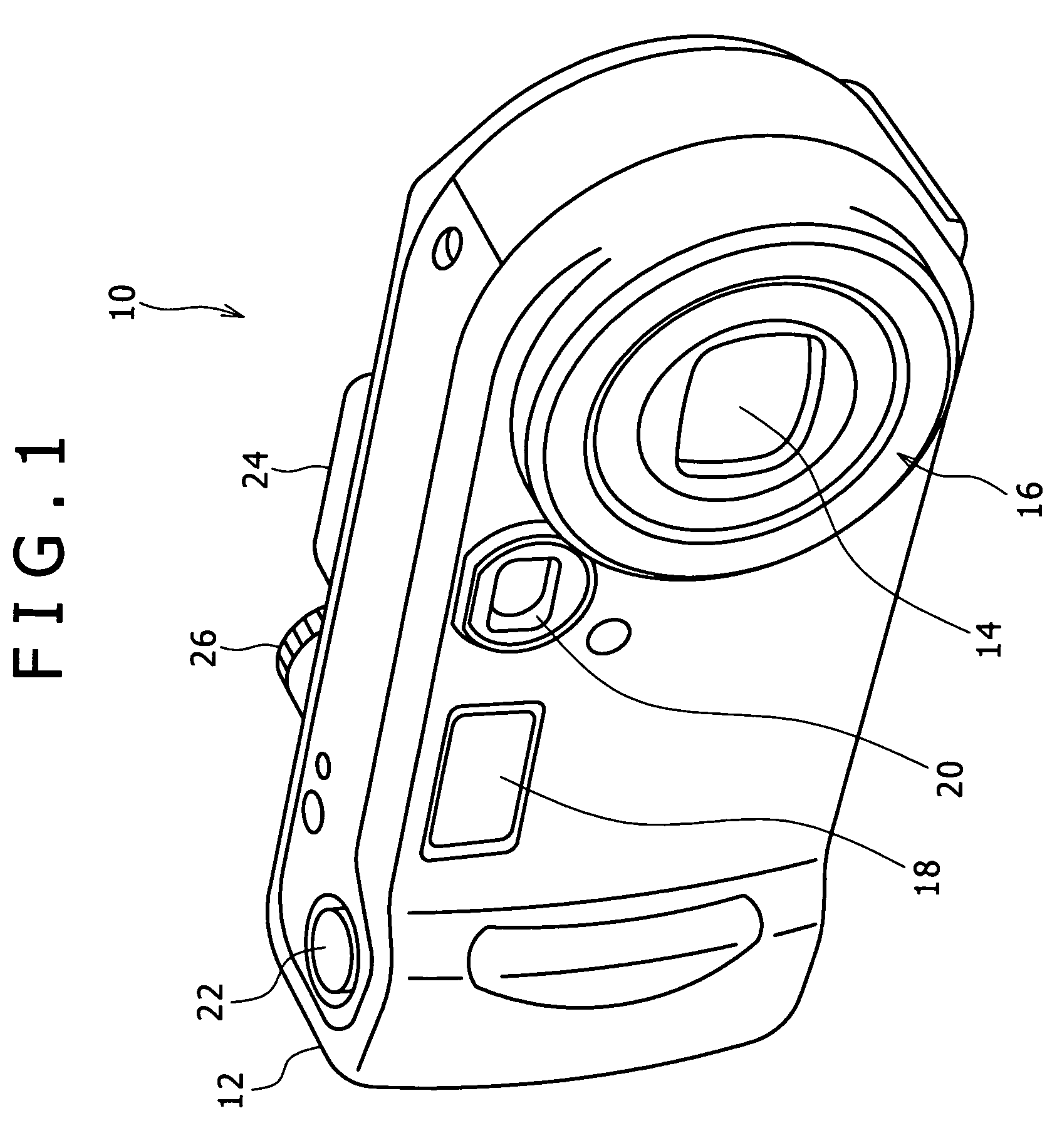
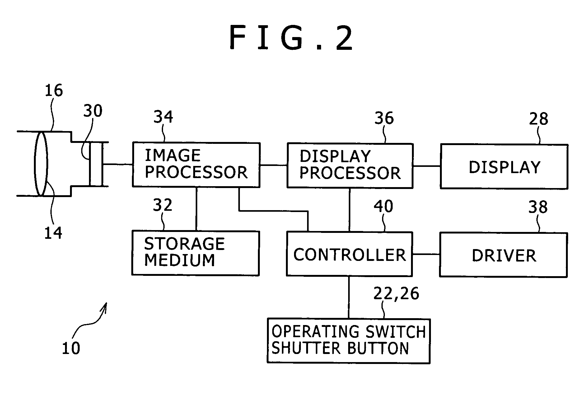
[0033]FIG. 1 is a perspective view illustrating an image pickup apparatus according to the present embodiment. FIG. 2 is a block diagram illustrating the structure of the image pickup apparatus of the present embodiment.

[0034]As illustrated in FIG. 1, an image pickup apparatus 10 of the present embodiment is a digital still camera, and it possesses a case 12 which constitutes the exterior of the camera body. It is assumed in the present specification that the subject side is the front and the opposite side is the back.

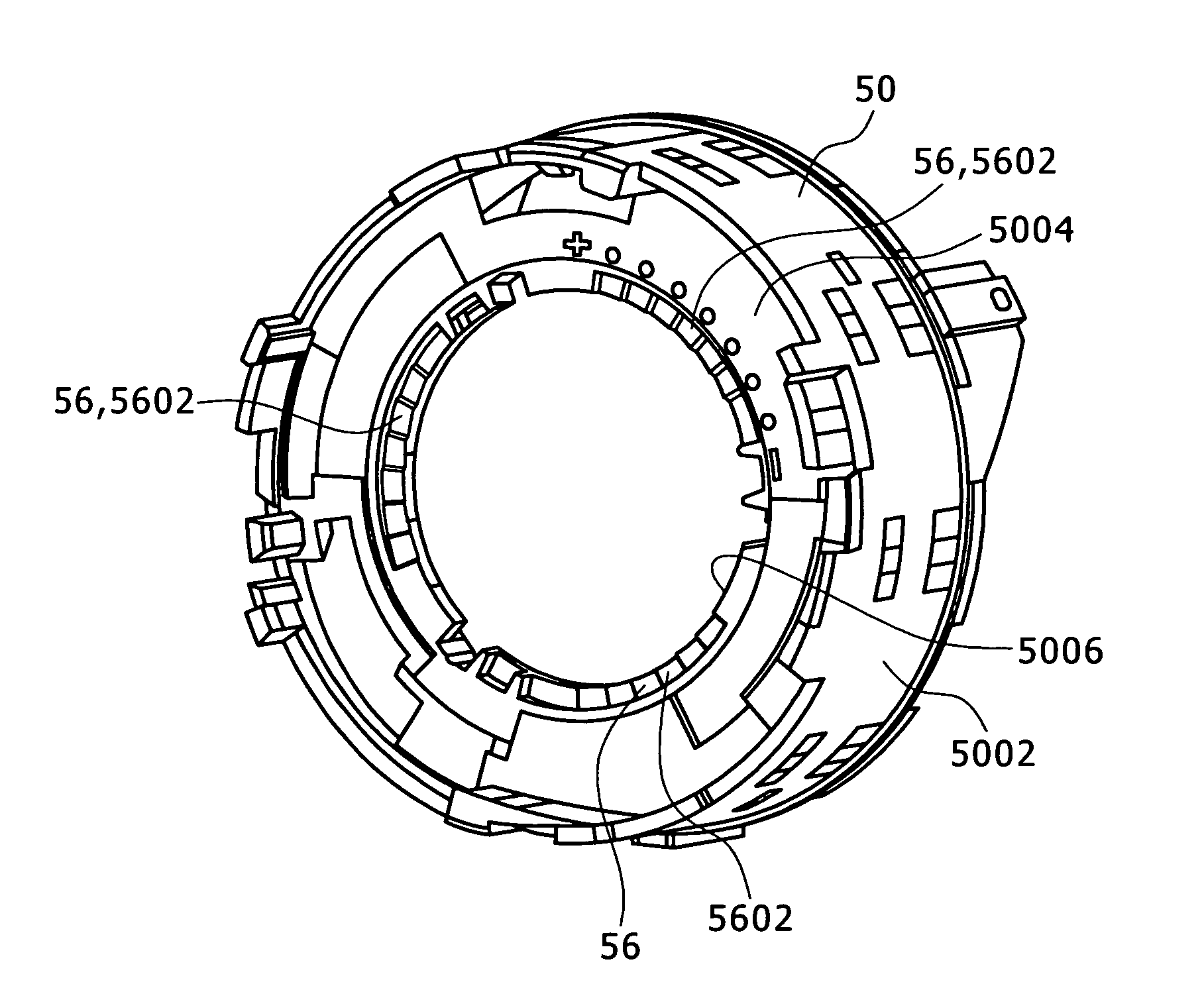
[0035]A lens barrel 16 which includes a shooting optical system 14 is provided in the front right side of the case 12. An image sensor 30 (FIG. 2) which pictures a subject image led by the shooting optical system 14 is provided in the back end of the lens barrel 16.

[0036]A flash unit 18 which emits a flashlight, an objective lens 20 of an optical viewfinder, etc. are ...


PUM


Abstract

A lens barrel includes a shooting optical system contained in a barrel and operable to lead a subject image to an image sensor, a back focus adjustment lens group constituting a part of the shooting optical system and operable to be fixed immovably after the position of the back focus adjustment lens group is adjusted in an optical axis direction of the shooting optical system, and a back focus adjustment mechanism operable to adjust the position of the back focus adjustment lens group in the optical axis direction.

Description

CROSS REFERENCES TO RELATED APPLICATIONS[0001]The present invention contains subject matter related to Japanese Patent application JP 2007-212772 filed in the Japanese Patent Office on Aug. 17, 2007, the entire contents of which are incorporated herein by reference.BACKGROUND OF THE INVENTION[0002]1. Field of the Invention[0003]The present invention relates to a lens barrel and an image pickup apparatus.[0004]2. Description of the Related Art[0005]Image pickup apparatuses, such as a digital still camera and a video camera, are provided with a lens barrel containing a shooting optical system which leads a subject image to an image sensor.[0006]Such a lens barrel is designed so that a focus position (a back focus position or a focusing position) of the shooting optical system for the distance of a certain subject may become a predetermined design value (in other words, the position of an image surface of the subject image formed by the shooting optical system may become the predetermi...

Claims


Application Information

Patent Timeline
Patent Type & Authority Patents(United States)
IPC IPC(8): G02B7/02
CPCG02B7/08
Inventor KURODA, DAISUKE
Owner SONY CORP
Why Eureka
Try Eureka