
Separation apparatus, separation system, separation method and non-transitory computer readable storage medium

a computer-readable storage medium and separation method technology, applied in the direction of solid-state devices, chemistry apparatus and processes, layered products, etc., can solve the problems of large jetting pressure, wafer or the supporting substrate may be damaged, and the wafer has been thinned and thus more likely to be damaged, so as to achieve appropriate and efficient separation processing of the processing target substrate and the supporting substrate.

Inactive Publication Date: 2014-09-25
TOKYO ELECTRON LTD
View PDF15 Cites 0 Cited by
  • Summary
  • Abstract
  • Description
  • Claims
  • Application Information

AI Technical Summary

Benefits of technology

[0009]The present invention has been made in consideration of the above points and its object is to appropriately and efficiently perform separation processing of a processing target substrate and a supporting substrate.
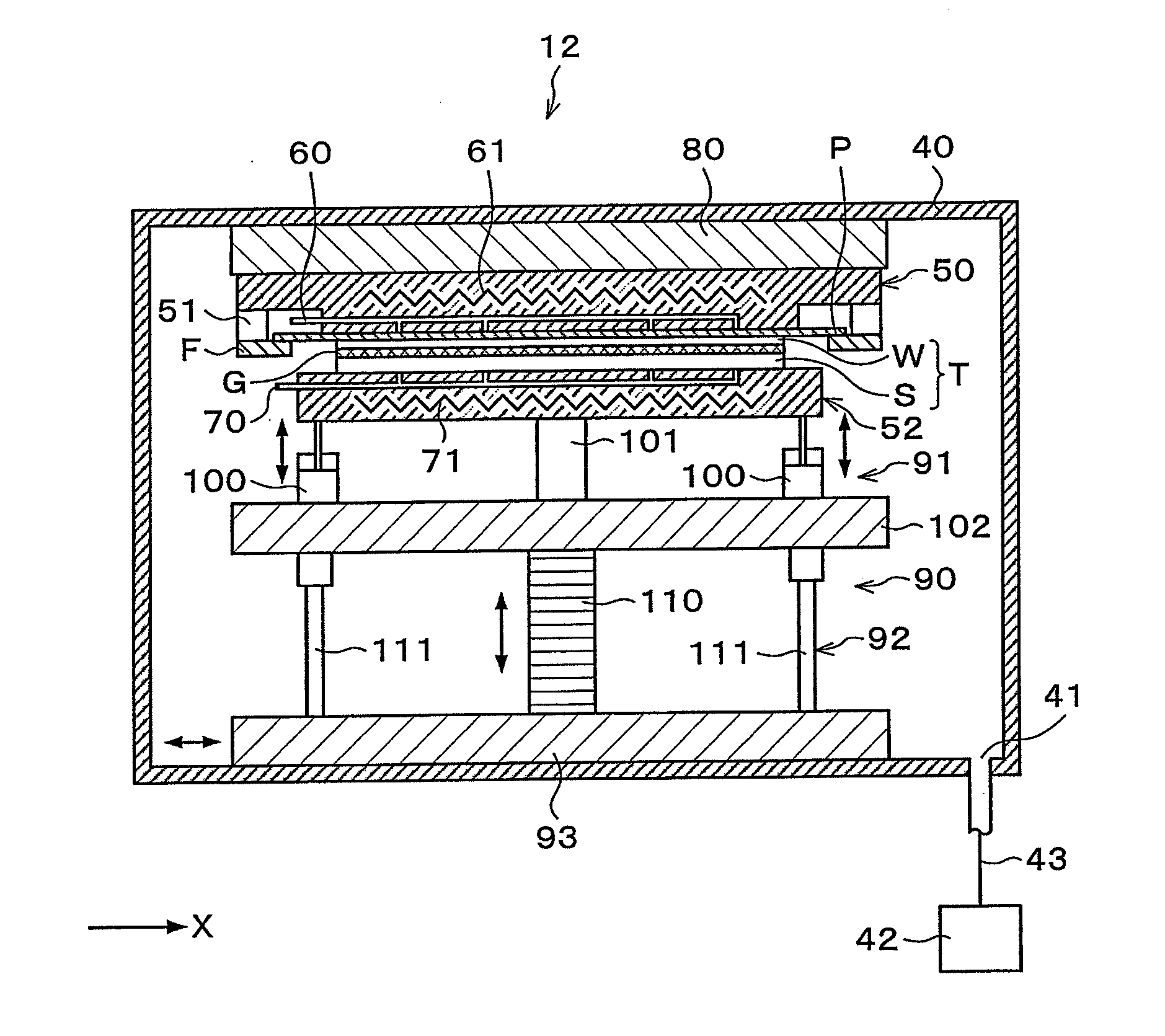
[0011]According to the present invention, it is possible to move the outer peripheral portion of the another holding part in the vertical direction, while the processing target substrate is held by the one holding part and the supporting substrate is held by the another holding part, to continuously separate the supporting substrate from the processing target substrate starting from an outer peripheral portion toward a central portion of the supporting substrate. In this case, no physical load is directly applied to the processing target substrate and the supporting substrate in separating the superposed substrate. In addition, it is possible to continuously separate the supporting substrate from the processing target substrate and thereby easily separate the supporting substrate from the processing target substrate with a smaller load than that in a prior art. Therefore, it is possible to appropriately and uniformly separate the supporting substrate from the processing target substrate without damaging the processing target substrate. Further, the time period required for the separation processing can be made shorter than that in the prior art. As described above, according to the present invention, it is possible to appropriately and efficiently perform separation processing of the processing target substrate and the supporting substrate.
[0016]According to the present invention, it is possible to appropriately and efficiently perform separation processing of a processing target substrate and a supporting substrate.

Problems solved by technology

H9-167724, liquid is jetted at a jetting pressure larger than a joint strength, so that the wafer or the supporting substrate may be damaged.
In particular, the wafer has been thinned and is thus more likely to be damaged.
Further, in the case where the wafer and the supporting substrate are joined together, for example, via an adhesive, the joint strength between the wafer and the supporting substrate is large, so that the liquid at an extremely large jetting pressure is required and a lot of time is necessary to separate the wafer from the supporting substrate.

Method used


Image

  • Separation apparatus, separation system, separation method and non-transitory computer readable storage medium
  • Separation apparatus, separation system, separation method and non-transitory computer readable storage medium
  • Separation apparatus, separation system, separation method and non-transitory computer readable storage medium

Examples


Embodiment Construction

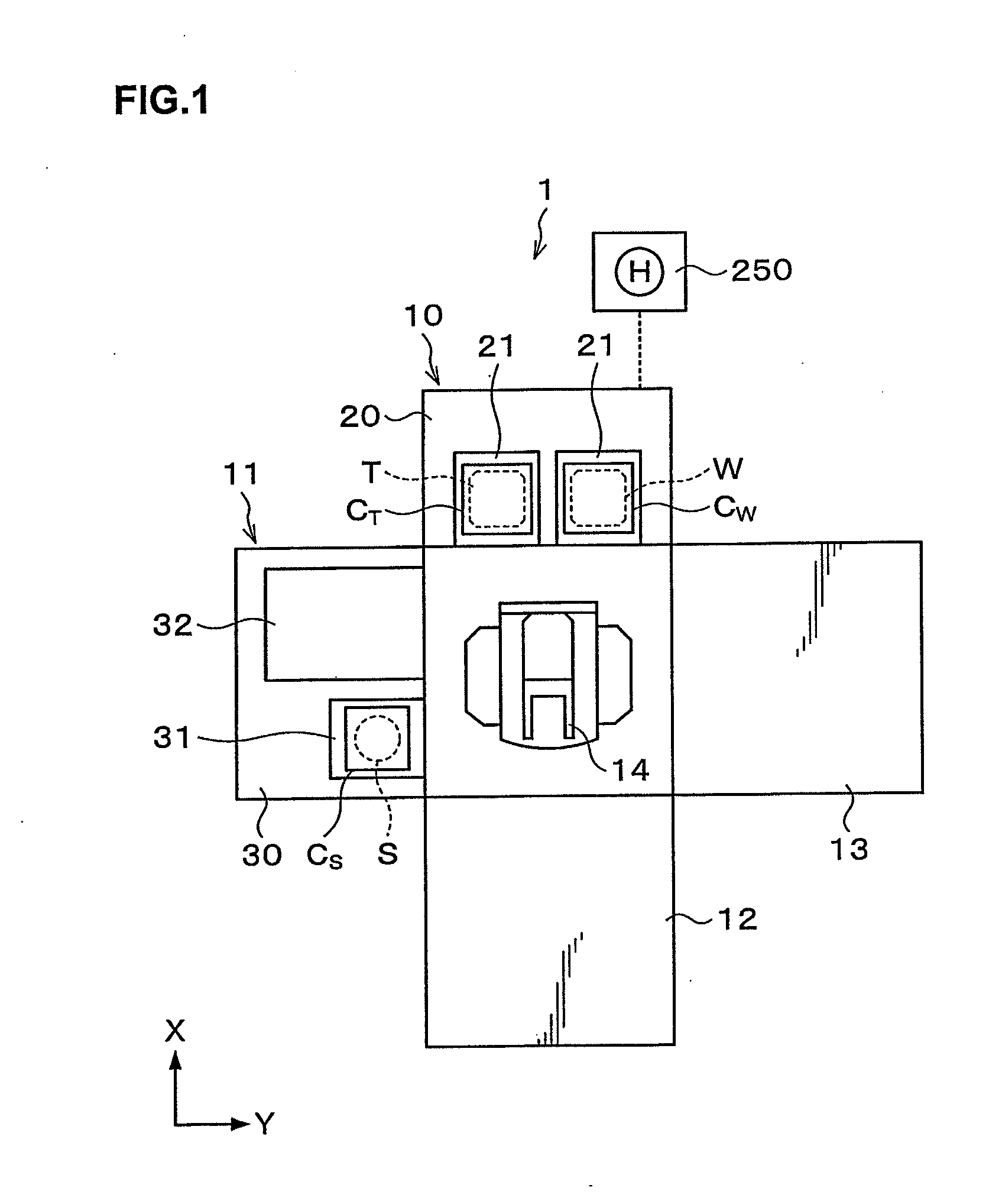
[0064]Hereinafter, embodiments of the present invention will be described. FIG. 1 is a plan view illustrating the outline of the configuration of a separation system 1 according to this embodiment.

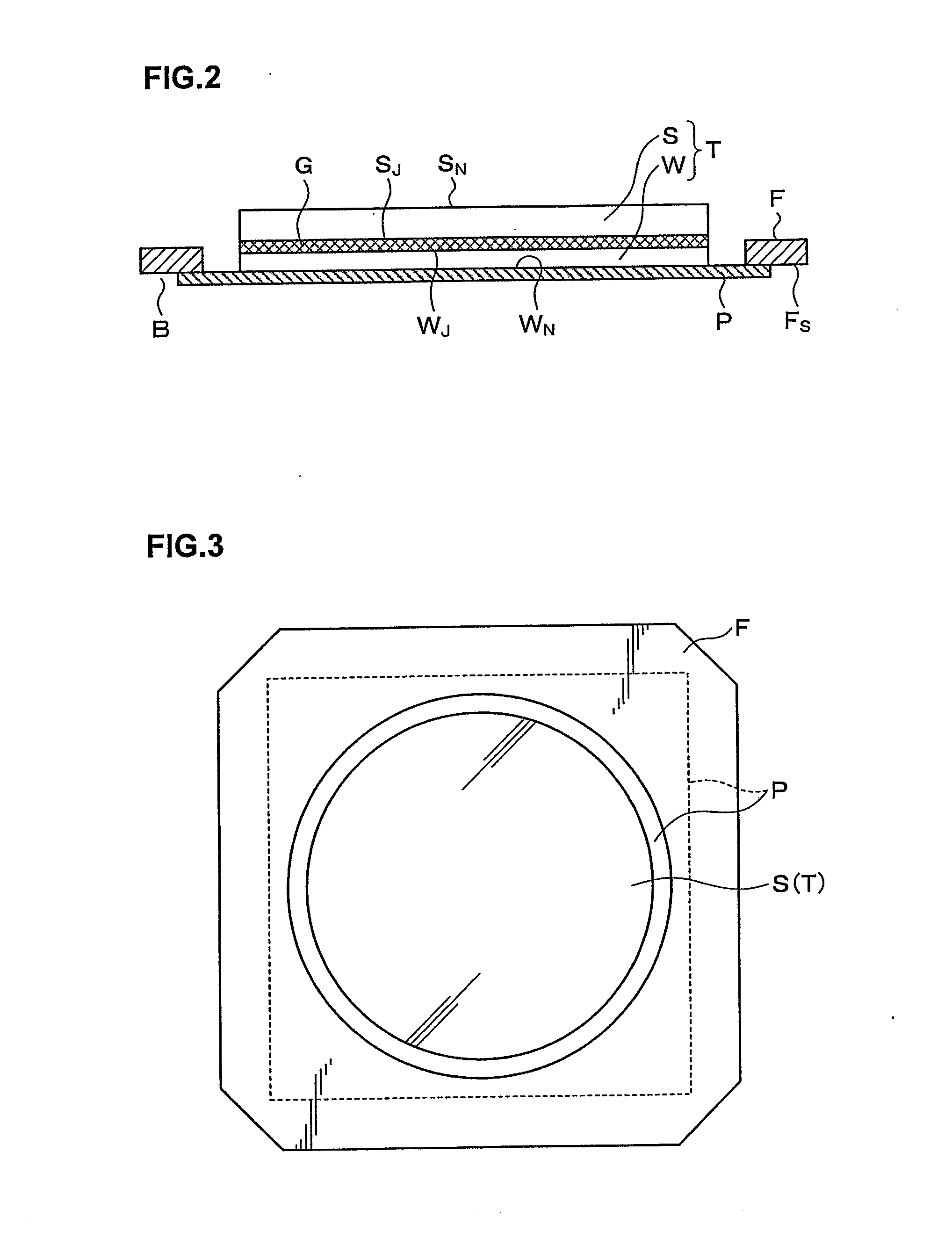
[0065]In the separation system 1, a superposed wafer T as a superposed substrate in which a processing target wafer W as a processing target substrate and a supporting wafer S as a supporting substrate are joined together with an adhesive G as illustrated in FIG. 2 and FIG. 3 is separated into the processing target wafer W and the supporting wafer S. Hereinafter, in the processing target wafer W, the surface to be joined with the supporting wafer S via the adhesive G is referred to as a “joint surface WJ” and the surface opposite to the joint surface WJ is referred to as “a non-joint surface WN.” Similarly, in the supporting wafer S, the surface to be joined with the processing target wafer W via the adhesive G is referred to as a “joint surface SJ” and the surface opposite to the joint su...


PUM

PropertyMeasurementUnit
thicknessaaaaaaaaaa
temperatureaaaaaaaaaa
diameteraaaaaaaaaa

Abstract

A separation apparatus for separating a superposed substrate into a processing target substrate and a supporting substrate, includes: one holding part holding the processing target substrate via a tape; another holding part holding the supporting substrate; and a moving mechanism moving the another holding part in a vertical direction while holding an outer peripheral portion thereof to continuously separate the supporting substrate held by the another holding part from the processing target substrate held by the one holding part starting from an outer peripheral portion toward a central portion of the supporting substrate, wherein the moving mechanism includes: a first moving part holding the another holding part and moving only the outer peripheral portion of the another holding part in the vertical direction; and a second moving part moving the first moving part and the another holding part in the vertical direction.

Description

BACKGROUND OF THE INVENTION[0001]1. Field of the Invention[0002]The present invention relates to a separation apparatus for separating a superposed substrate into a processing target substrate and a supporting substrate while the superposed substrate is placed inside an annular frame and held by a tape bonded to a surface of the frame and a non-joint surface of the processing target substrate, a separation system including the separation apparatus, a separation method using the separation apparatus, and a non-transitory computer readable storage medium.[0003]This application is based upon and claims the benefit of priority of the prior Japanese Patent Application No. 2011-147263, filed in Japan on Jul. 1, 2011, and the prior Japanese Patent Application No. 2012-100857, filed in Japan on Apr. 26, 2012, the entire contents of which are incorporated herein by reference.[0004]2. Description of the Related Art[0005]In recent years, for example, in a manufacturing process of a semiconduct...

Claims


Application Information

Patent Timeline
Patent Type & Authority Applications(United States)
IPC IPC(8): B32B43/00
CPCH01L21/67051B32B43/006H01L21/67092Y10T156/1153Y10T156/1168Y10T156/1911Y10T156/1978Y10T156/1994H01L21/302B32B38/10H01L21/673H01L21/67346H01L2221/683H01L2221/68304H01L2221/68318
Inventor SOMA, YASUTAKAYOSHITAKA, NAOTOKOMEDA, HIROSHIMANABE, EIJIHIRAKAWA, OSAMUDEGUCHI, MASATOSHITAMURA, TAKESHI
Owner TOKYO ELECTRON LTD
Learn More