Fuel dispenser

a fuel dispenser and fuel technology, applied in the field of fuel dispensers, can solve the problems of fuel dispensers not including the necessary control electronics, the contact of keypads may also corrode, and the conductivity of contacts may also be los

Active Publication Date: 2011-05-24
GILBARCO
View PDF53 Cites 35 Cited by
  • Summary
  • Abstract
  • Description
  • Claims
  • Application Information

AI Technical Summary

Benefits of technology

[0072]In other embodiments, a virtual display system may be implemented in dispenser 10. Referring to FIGS. 13 and 14, virtual display systems project a keyboard or other input device into the air or onto another surface and then monitor the virtual keyboard for a user's touch of the virtual keys to detect the customer's desired input. For example, a laser system may be used that is capable of both scanning and projecting laser light onto a surface that is secure with respect to viewing angle. Based on initial input provided by the customer either directly into dispenser 10 by reader 20 or indirectly by a wireless connection, the laser system and software would dynamically present the required virtual key layout based on the type of transaction, user preferences, ease of use, or other pre-defined parameters. The laser would be capable of projecting and auto focusing so that it can simultaneously project on a number of surfaces with varying levels of distance, content, and required resolution, for example on the car window, door panel or any other surface capable of receiving the projected laser light.

Problems solved by technology

Unfortunately, the vast majority of fuel dispensers already in existence include displays and associated input devices that are insufficient for supporting web-based interaction.
Further, many of the fuel dispensers fail to include the necessary control electronics to readily support such interaction.
Shoulder surfing subjects customers of fuel dispensers to theft of identifying information associated with payment accounts and PINs.
Additionally, keypads of fuel dispensers wear out over time due to continuous and repeated action of their keys by customers.
With use, the contacts within a keypad may also corrode and lose their conductivity.
As such, fuel dispensers are plagued with a costly replacement schedule for user interface keypads.
However, prior art speakers are loud and omni-directional so that sound from one dispenser interferes with sound generated from another dispenser.

Method used


Image

  • Fuel dispenser
  • Fuel dispenser
  • Fuel dispenser

Examples


Embodiment Construction

[0033]Reference will now be made in detail to presently preferred embodiments of the invention, one or more examples of which are illustrated in the accompanying drawings. Each example is provided by way of explanation of the invention, not limitation of the invention. In fact, it will be apparent to those skilled in the art that modifications and variations can be made in the present invention without departing from the scope or spirit thereof. For instance, features illustrated or described as part of one embodiment may be used on another embodiment to yield a still further embodiment. Thus, it is intended that the present invention covers such modifications and variations. Additional aspects and advantages of the invention will be set forth in part in the description which follows and, in part, will be obvious from the description, or may be learned by practice of the invention.

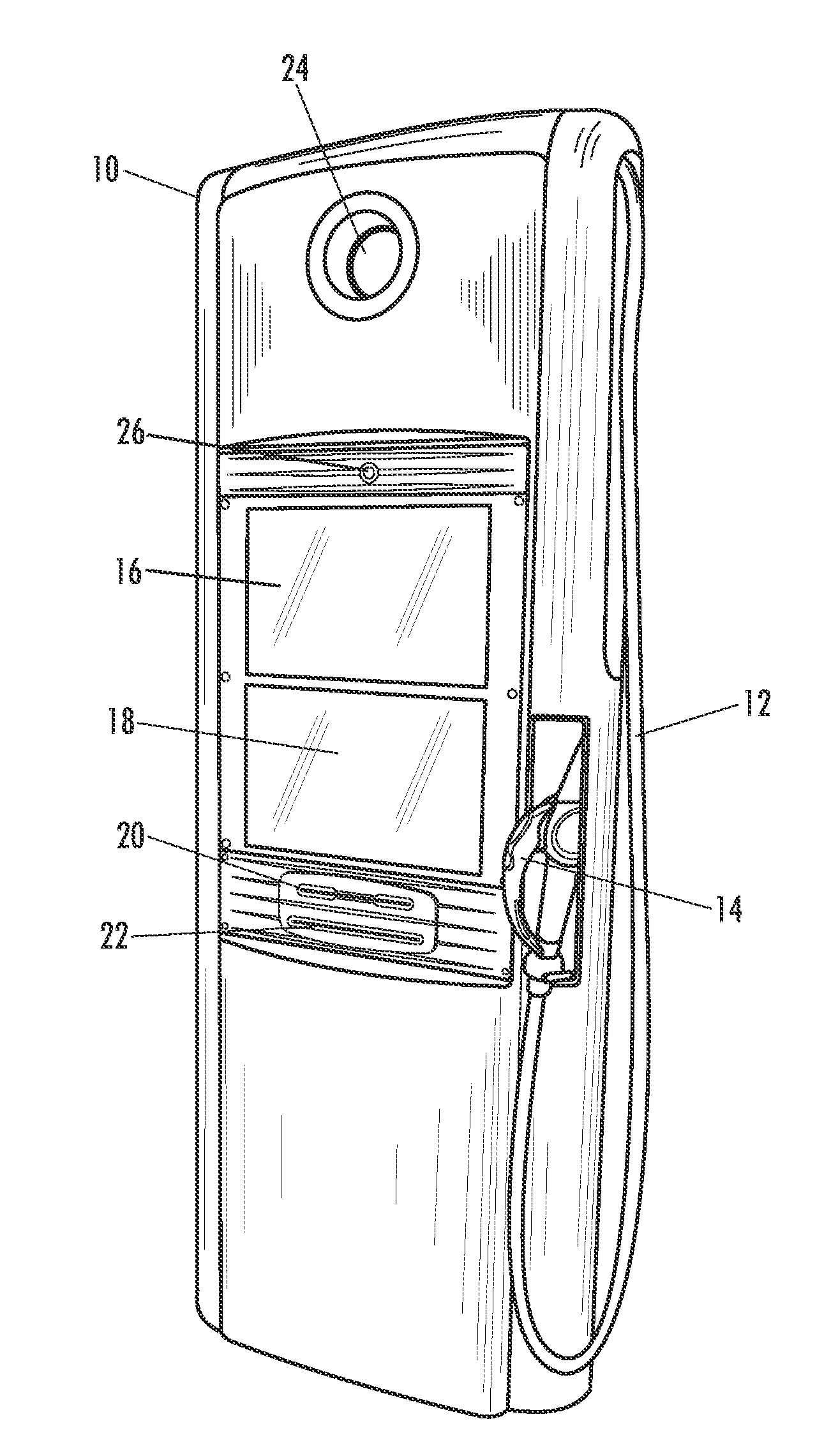
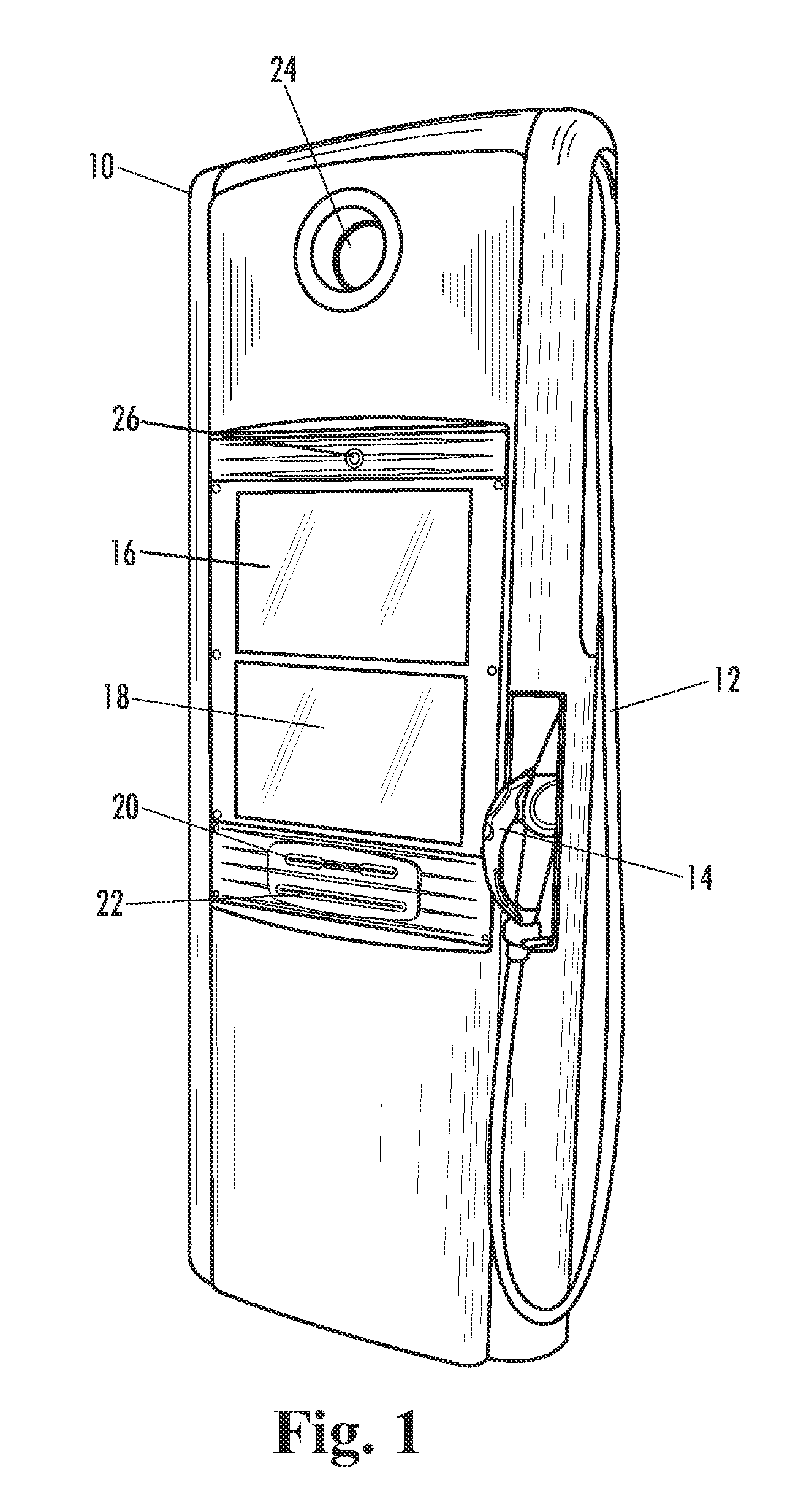
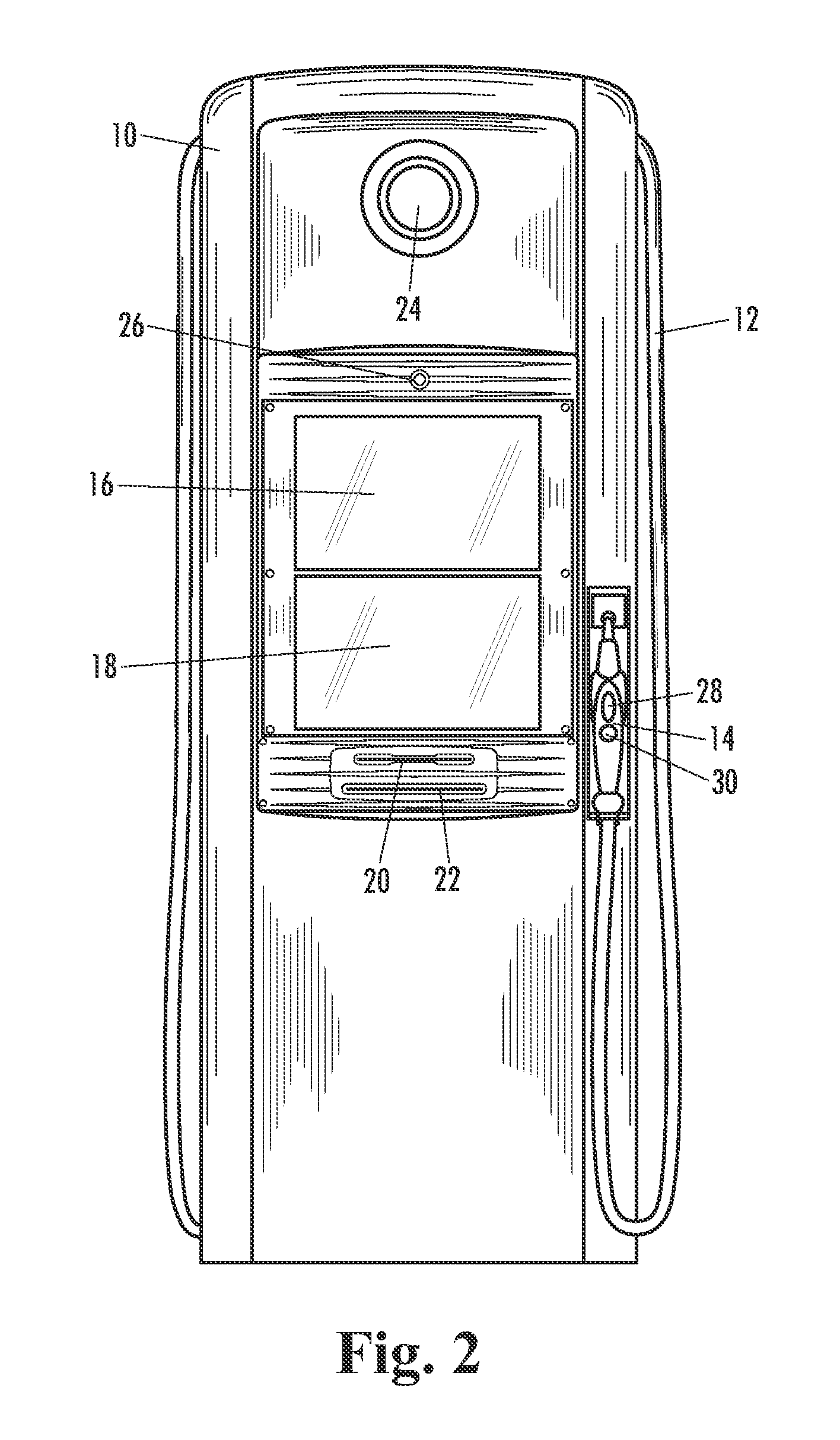
[0034]Referring to FIGS. 1-3, a fuel dispenser 10 is shown having a generally rectangular body, a fuel ...


PUM


Abstract

A fuel dispenser comprising a housing, a fuel dispensing apparatus mounted within the housing, control electronics operatively connected to the fuel dispensing apparatus, at least one display mounted in the housing and operatively coupled to the control electronics, and a nozzle operatively coupled to the fuel dispensing apparatus and the fuel dispensing apparatus control electronics, the nozzle configured to produce electromagnetic signals. The dispenser is configured to trigger an alarm when the nozzle is brought into close proximity to the at least one display to prevent the user from using the nozzle to make data entries.

Description

[0001]The present application claims priority to U.S. Provisional Patent Application Ser. No. 60 / 956,072, filed Aug. 15, 2007, entitled FUEL DISPENSER, the entire disclosure of which is incorporated by reference herein.FIELD OF THE INVENTION[0002]The present invention relates to dispensers and, more particularly, to fueling stations having advanced dispenser systems.BACKGROUND OF THE INVENTION[0003]In recent years, traditional fuel dispensers have evolved into elaborate point-of-sale (PoS) devices having sophisticated control electronics and user interfaces with larger displays and easier-to-use user interfaces. The fuel dispensers may include various types of payment means, such as card readers and cash acceptors, to expedite and further enhance fueling transactions. Further, customers are not limited to the purchase of fuel at these dispensers. Newer dispensers allow the customer to purchase services, such as car washes, and goods, such as fast food or convenience store products. ...

Claims


Application Information

Patent Timeline
Patent Type & Authority Patents(United States)
IPC IPC(8): G08B21/00B67D7/12B67D7/08B67D7/06B67D7/10B67D7/22B67D7/30B67D7/84
CPCB67D7/08B67D7/14B67D7/145B67D7/346B67D7/348G06Q20/10G07G3/00G06Q30/0601G06Q50/06G07F7/1041G07F9/026G07F13/025G06Q20/20G07F9/0235
Inventor DELINE, JONATHAN E.
Owner GILBARCO
Why Eureka
Try Eureka