Zoom lens and imaging apparatus

a zoom lens and imaging apparatus technology, applied in the field of zoom lenses, can solve problems such as high cost, and achieve the effects of reducing aberrations, reducing costs, and reducing costs

Inactive Publication Date: 2014-06-26
FUJIFILM CORP
View PDF1 Cites 3 Cited by
  • Summary
  • Abstract
  • Description
  • Claims
  • Application Information

AI Technical Summary

Benefits of technology

[0054]The above advantageous effects will become more prominent particularly in the case that Conditional Formula (1-2) is satisfied within the range defined in Conditional Formula (1-1).
[0055]Further, the first zoom lens of the present invention exhibits the following advantageous effects by satisfying Conditional Formula (2-1). Conditional Formula (2-1) determines the relationship between the focal length of the entire system at the wide angle end and the focal length of the first lens group. If the value of |fw / f1| is less than or equal to the lower limit defined in Conditional Formula (2-1), the negative refractive power of the first lens group will become weak. This will result in the optical system as a whole becoming larger, which is not preferable. Inversely, if the value of |fw / f1| is greater than or equal to the upper limit defined in Conditional Formula (2-1), the negative refractive power of the first lens group will be excessively strong. This will result in correction of various aberrations at off axis portions difficult, which is not favorable. The above shortcomings can be prevented in the case that Conditional Formula (2-1) is satisfied. That is, miniaturization of the optical system as a whole can be achieved, and various aberrations can be favorably corrected at off axis portions.
[0056]Note that the above advantageous effects will become more prominent in the case that Conditional Formula (2-2) is satisfied within the range defined by Conditional Formula (2-1).
[0057]In the second zoom lens according to the present invention, the first lens group is constituted by four lenses, which are the first lens having a negative refractive power, the second lens, the third lens having a negative refractive power, and the fourth lens having a positive refractive power, provided in this order from the object side, similarly to the first zoom lens. Thereby, suppressing increases of aberrations that accompany widening of an angle of view becomes possible while suppressing increases in cost.
[0058]In addition, the second zoom lens according to the present invention exhibits the following advantageous effects by satisfying Conditional Formula (1-3). Conditional Formula (1-3) determines the relationship between the focal length of the first lens group and the focal length of the second lens group, similarly to Conditional Formula (1-1). If the value of |f1 / f2| is less than or equal to the lower limit defined in Conditional Formula (1-3), the refractive power of the second lens group will be weak. As a result, the amount of movement of the second lens group when changing magnification will increase, the total length of the optical system as a whole will become long, and miniaturization will become difficult, which is not preferable. Inversely, if the value of |f1 / f2| is greater than or equal to the upper limit defined in Conditional Formula (1-3), the refractive power of the first lens group will be insufficient. As a result, the necessity to increase the diameter of the first lens L11 positioned most toward the object side will arise in order to secure an angle of view and miniaturization will become difficult, which is not preferable. The foregoing shortcomings can be prevented in the case that Conditional Formula (1-3) is satisfied. That is, miniaturization of the optical system as a whole can be easily achieved.
[0059]The above advantageous effects will become more prominent in the case that Conditional Formula (1-2) is satisfied within the range defined in Conditional Formula (1-3).

Problems solved by technology

However, the zoom lens of U.S. Pat. No. 5,844,724 has a long total length and a large number of lenses, resulting in high cost.

Method used


Image

  • Zoom lens and imaging apparatus
  • Zoom lens and imaging apparatus
  • Zoom lens and imaging apparatus

Examples


fourth embodiment

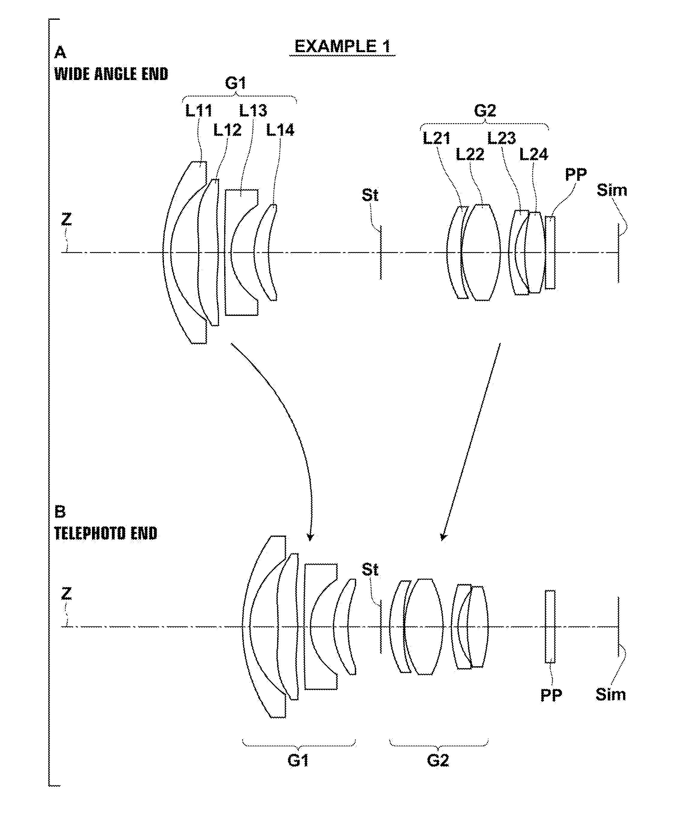
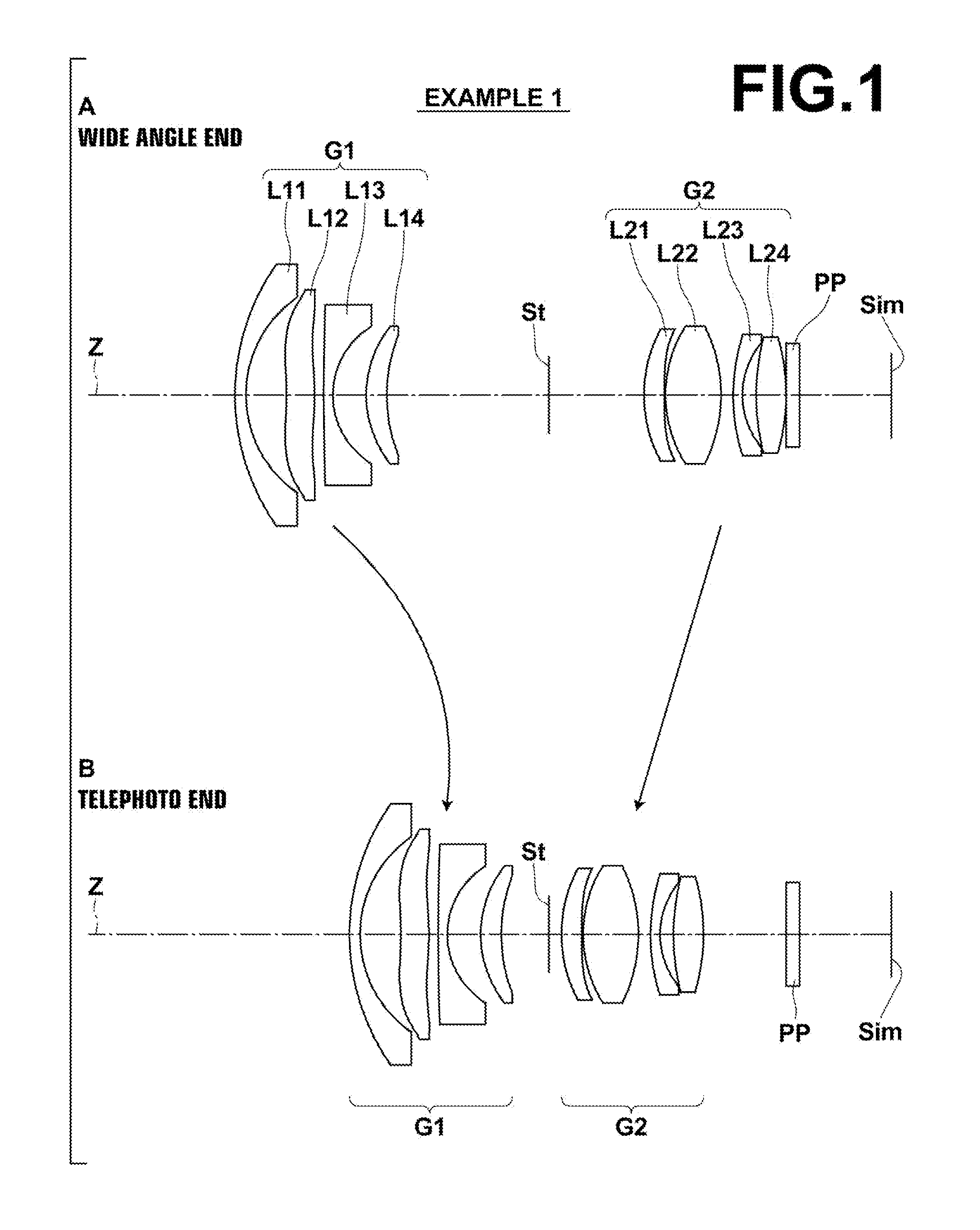
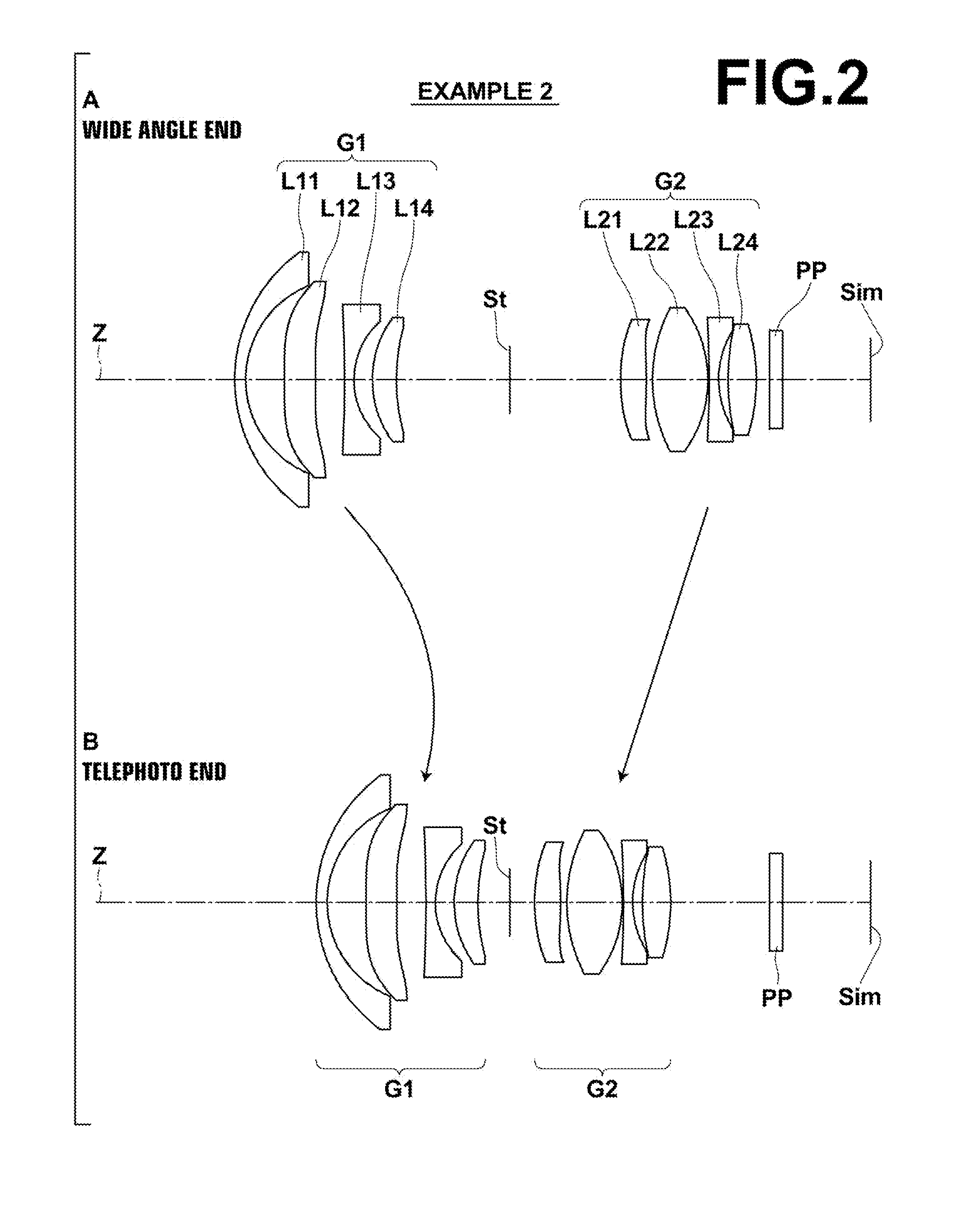
[0095]The first lens group G1 is constituted by a first lens L11 having a negative refractive power, a second lens L12 having a positive refractive power, a third lens L13 having a negative refractive power, and a fourth lens L14 having a positive refractive power, provided in this order from the object side. Here, the first lens L11 may be a negative meniscus shaped lens, the second lens L12 may be a lens having an aspherical surface toward the object side and an aspherical surface toward the image side, the third lens L13 may be a negative meniscus shaped lens, and the fourth lens L14 may be a positive meniscus shaped lens, as illustrated in the example illustrated in FIG. 1. Note that the fourth embodiment employs a lens having a negative refractive power as the second lens L12.

second embodiment

[0096]The surface of the second lens L12 toward the object side is of an aspherical shape which is concave toward the object side in a paraxial region. In addition, at least one of the surface of the second lens L12 toward the object side and the surface of the second lens L12 toward the image side is of an aspherical shape with at least one inflection point within a range from the center to the effective diameter thereof (both surfaces in the example of FIG. 1). Note that particularly in the second embodiment, the surface of the second lens L12 toward the object side is convex toward the object side in the paraxial region and is of an aspherical shape that does not have any inflection points within a range from the center to the effective diameter thereof.

[0097]Meanwhile, the second lens group G2 is constituted by a first lens L21 having a positive refractive power, a second lens L22 having a positive refractive power, a third lens L23 having a negative refractive power, and a four...


PUM


Abstract

A zoom lens includes: a first lens group having a negative refractive power; and a second lens group having a positive refractive power, provided in this order from an object side. Magnification is changed by moving the first lens group and the second lens group. The first lens group includes a first lens having a negative refractive power, a second lens, a third lens having a negative refractive power, and a fourth lens having a positive refractive power, provided in this order from the object side. The zoom lens satisfies predetermined conditional formulae.

Description

CROSS REFERENCE TO RELATED APPLICATIONS[0001]This application is a continuation of PCT / JP2012 / 005377 filed on Aug. 28, 2012, which claims priority to Japanese Application No. 2011-185742 filed on Aug. 29, 2011. The entire contents of each of the above applications are hereby incorporated by reference.TECHNICAL FIELD[0002]The present invention is related to a zoom lens. Particularly, the present invention is related to a zoom lens which can be favorably utilized in miniature video cameras.[0003]The present invention is also related to an imaging apparatus equipped with such a zoom lens.BACKGROUND ART[0004]Conventionally, zoom lenses of the two group type, constituted by a first lens group having a negative refractive power and a second lens group having a positive refractive power in this order from an object side, that change magnification by moving the first lens group and the second lens group in the direction of the optical axis, are known as zoom lenses having variable magnifica...

Claims


Application Information

Patent Timeline
Patent Type & Authority Applications(United States)
IPC IPC(8): G02B15/14
CPCG02B15/14G02B15/177G02B15/1425
Inventor SAITO, HIROKICHO, MICHIOITO, TORU
Owner FUJIFILM CORP
Why Eureka
Try Eureka