Polarizing plate, method for manufacturing same and liquid-crystal display device comprising same

a technology of liquid crystal display device and polarizing plate, which is applied in the direction of polarising elements, instruments, other domestic objects, etc., can solve the problems of deterioration of the contrast ratio (cr) of the liquid crystal display apparatus, increased production costs, and increased production costs of tac films. achieve the effect of reducing rainbow spots, improving image quality, and ensuring viewing angl

Active Publication Date: 2019-06-25
SAMSUNG SDI CO LTD
View PDF21 Cites 2 Cited by
  • Summary
  • Abstract
  • Description
  • Claims
  • Application Information

AI Technical Summary

Benefits of technology

[0030]The present invention provides a polarizing plate, a method of preparing the same, and an optical display apparatus including the same that can suppress rainbow spots, secure viewing angle, improve an image quality, and improve polarization degree of the polarizer and transmittance, thereby having excellent optical properties and high contrast ratio. Further, the present invention provides a polarizing plate, a method of preparing the same, and an optical display apparatus including the same that may be no deterioration of polarization degree thereof, or able to minimize the deterioration, and thus the polarizing plate can suppress rainbow spots, even if the polarizing plate is exposed to high temperature. More further, the present invention provides a polarizing plate, a method of preparing the same, and an optical display apparatus including the same having high economic feasibility by using the drawn polyester film as a protective film for the polarizing plate over the whole orientations.

Problems solved by technology

Typically, although the protective film is a triacetyl cellulose (TAC) film, the TAC film is more expensive than typical polymer films.
However, the common pet film which is drawn in md and td has high molecular orientation angle, and thus there is a large deviation between an absorption axis of a polarizer and an optical axis of the pet film.
Further, due to this, contrast ratio (cr) of the liquid crystal display apparatus may be deteriorated.
Still further, the common PET film may decrease polarization degree of the polarizer and transmittance of the polarizing plate and make rainbow spots worse, when exposed at high temperature for a long period of time.
Moreover, when the PET film is drawn, a portion of, particularly, an end portion of the PET film may suffer from deterioration in optical properties due to its asymmetric molecular orientation in incorporating into a polarizing plate, and thus, there has been a limitation in its use.
Further, since the PET film is a drawn film, the film can suffer from rainbow spots in using it in liquid crystal display apparatus.

Method used


Image

  • Polarizing plate, method for manufacturing same and liquid-crystal display device comprising same
  • Polarizing plate, method for manufacturing same and liquid-crystal display device comprising same

Examples


examples 1 to 4

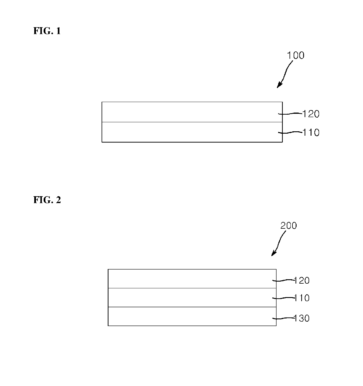
[0088]A polyvinyl alcohol film was drawn to a drawing ratio of 3 at 60° C., iodine was adsorbed onto the polyvinyl alcohol film, followed by drawing to a drawing ratio of 2.5 in a boric acid solution of 40° C., thereby preparing a polarizer. Then, a triacetyl cellulose film was stacked on one side of the polarizer using an adhesive (Z-200, NIPPON GOSHEI Co., Ltd.), and a polyethylene terephthalate film shown in Table 1 was stacked on the other side of the polarizer using an adhesive (Z-200, NIPPON GOSHEI Co., Ltd.) thereby preparing a polarizing plate.

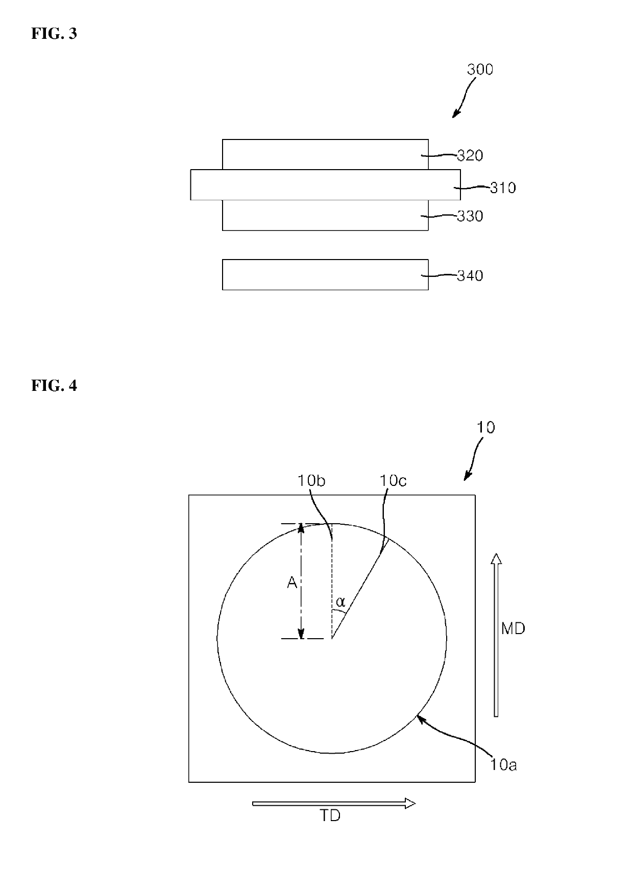
[0089]Polyethylene terephthalate film shown in Table 1 was prepared by melt-extruding a polyethylene terephthalate resin, drawing the melt-extruded film to a draw ratio of 6.1 in TD but not in MD while mechanically moving the film in MD using a roll, under the conditions listed in Table 1, followed by tension-relaxation treatment. The polyethylene terephthalate film had a thickness of 80 μm.

[0090]The maximum thermal shrinkage and maxim...


PUM

PropertyMeasurementUnit
thermal shrink angleaaaaaaaaaa
refractive indexaaaaaaaaaa
thicknessaaaaaaaaaa

Abstract

The present invention relates to a polarizing plate including a polarizer and a polyester film formed on an upper side of the polarizer, wherein the polyester film has a maximum thermal shrink angle of about 10° or less, and any one of a refractive index of x-axis direction nx at a wavelength of 550 nm and a refractive index of y-axis direction ny at a wavelength of 550 nm of about 1.65 or more; a method of preparing the polarizing plate; and a liquid crystal display apparatus comprising the polarizing plate.

Description

CROSS-REFERENCE TO RELATED APPLICATION(S)[0001]This application is a national stage and claims priority to and the benefit of International Application No. PCT / KR2014 / 007487 filed on Aug. 12, 2014, which claims priority to and the benefit of Korean Patent Application No. 10-2013-0103080 filed Aug. 29, 2013 and Korean Patent Application No. 10-2014-0087803 filed Jul. 11, 2014, the entire contents of which are incorporated herein by reference.TECHNICAL FIELD[0002]The present invention relates to a polarizing plate, a method of preparing the same, and an optical display apparatus including the same.BACKGROUND ART[0003]Polarizing plates are used inside and outside a liquid crystal cell for purpose of controlling an oscillation direction of light in order to visualize display patterns of a liquid crystal display apparatus. The polarizing plate includes a polarizer, and a protective film, which is formed on at least one side of the polarizer. Typically, although the protective film is a t...

Claims


Application Information

Patent Timeline
Patent Type & Authority Patents(United States)
IPC IPC(8): G02B5/30B32B33/00B29C55/08B32B37/12B32B37/14G02F1/1335G02F1/13363
CPCG02B5/3083B32B33/00G02F1/133528G02F1/133634G02B5/3033B32B37/12B32B37/14B32B2307/42B32B2457/202B29C55/08B32B27/08B32B27/36B32B2307/418B32B2307/518B32B2457/20B29C63/02B29C2063/485B29L2011/0066B29L2031/3475B29D11/00B29D11/00644B32B27/38B32B37/00C09J133/08G02B5/30G02B5/305G02F1/1335G02F1/13363
Inventor SHIN, KWANG HOPARK, EUN SUSHIN, DONG YOONCHUNG, HAE RYONG
Owner SAMSUNG SDI CO LTD
Why Eureka
Try Eureka