

Inorganic fiber mat, holding sealer, sound absorber, and method for manufacturing inorganic fiber mat
a technology of holding sealer and inorganic fiber, which is applied in the direction of pipe protection by thermal insulation, machine/engine, textiles and paper, etc., can solve the problems of fiber scattering from the surface of the holding sealer, undesirably worsening working conditions,
- Summary
- Abstract
- Description
- Claims
- Application Information
AI Technical Summary
Benefits of technology
Problems solved by technology
Method used
Image

Examples
Embodiment Construction
[0025]The embodiments will now be described with reference to the accompanying drawings, wherein like reference numerals designate corresponding or identical elements throughout the various drawings.
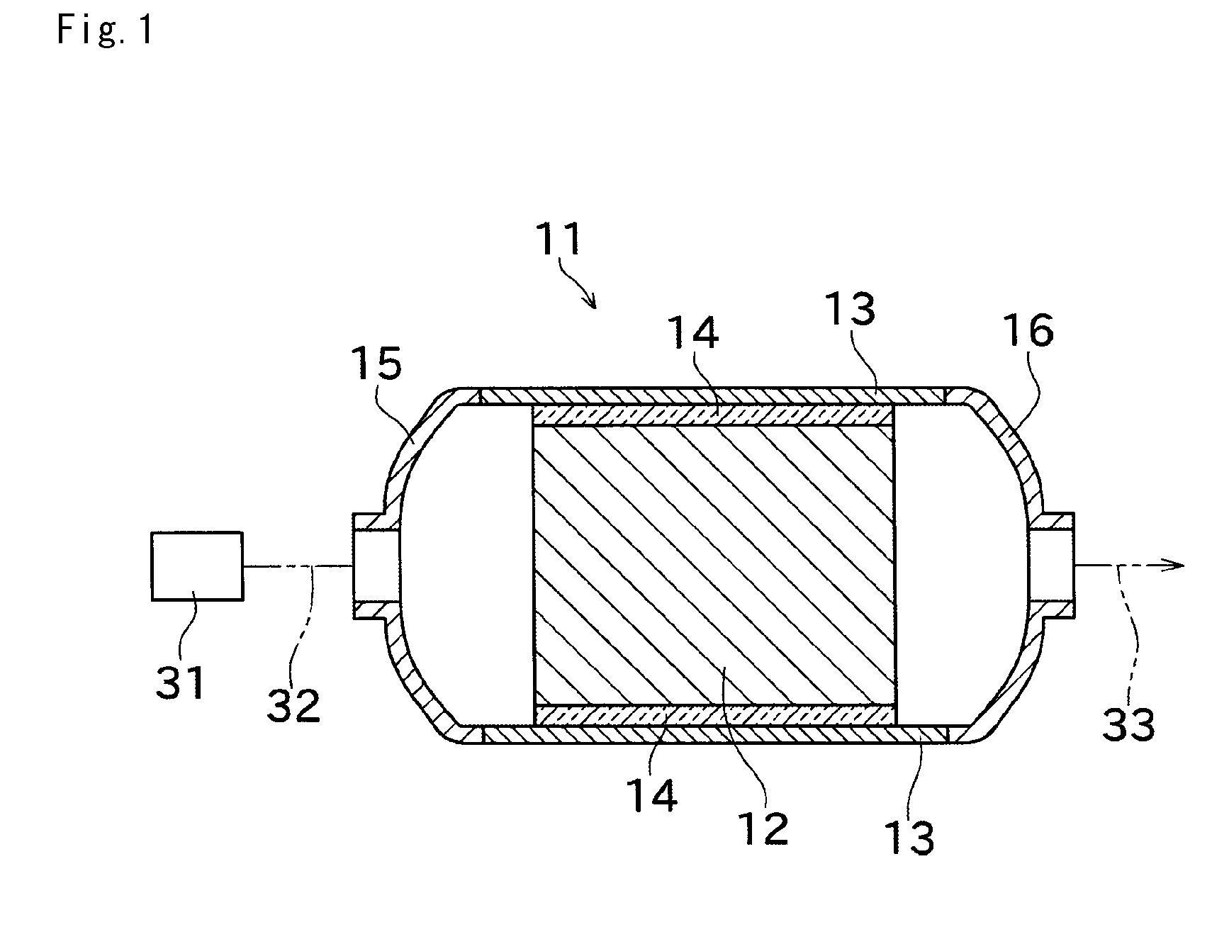
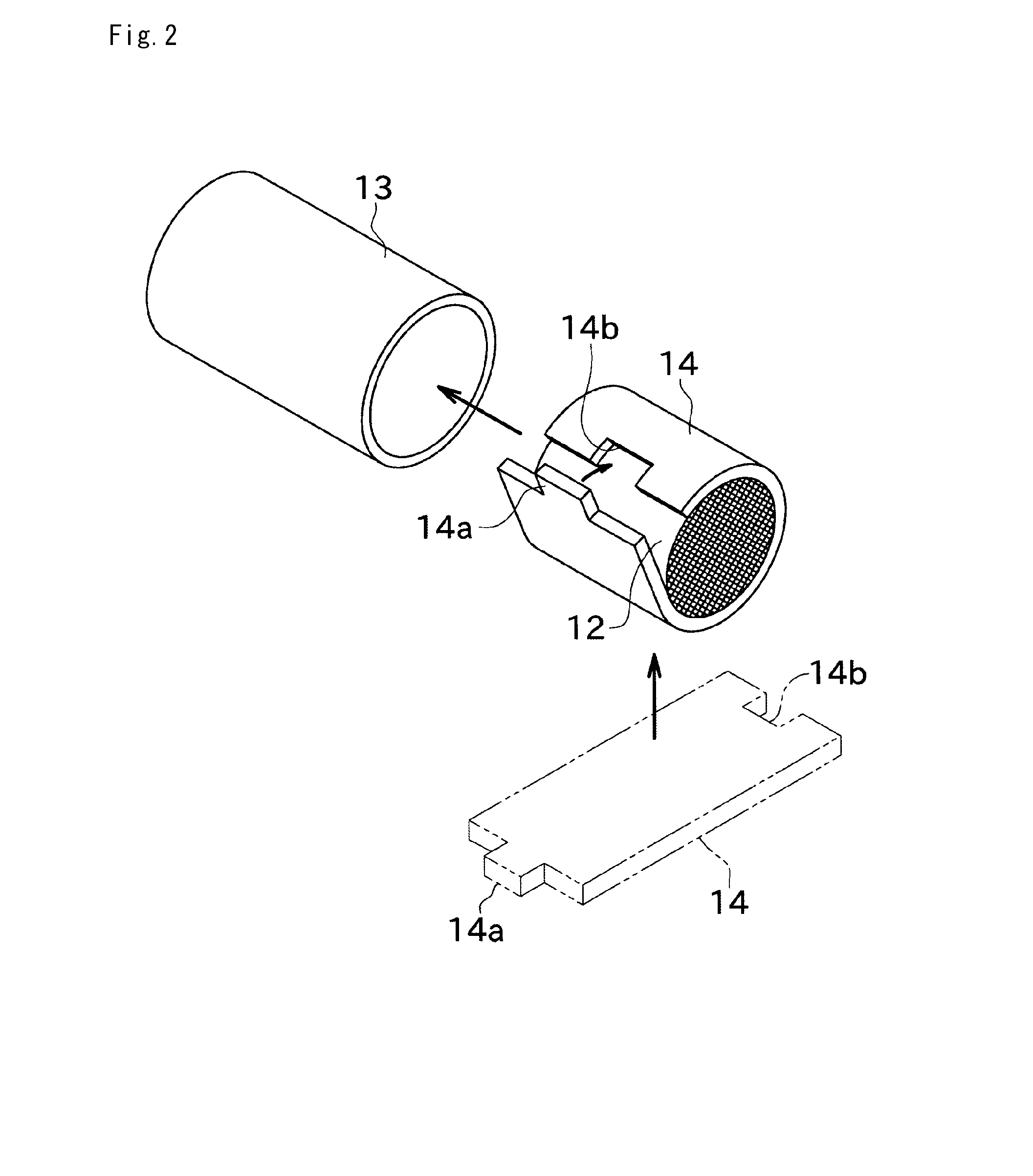
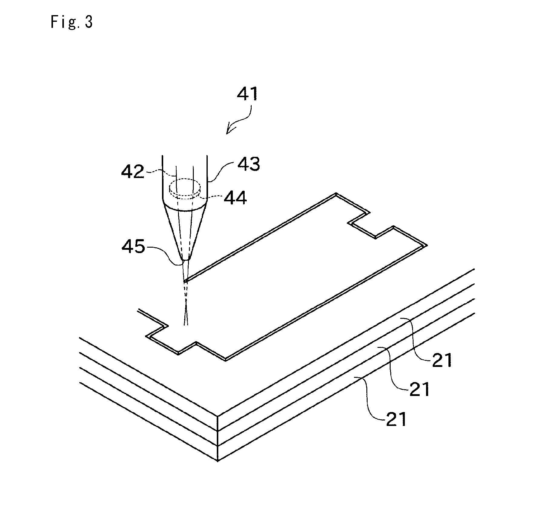
[0026]According to a first aspect in accordance with an embodiment of the present invention, there is provided an inorganic fiber mat formed by cutting an inorganic fiber aggregated body, wherein inorganic fibers existing on at least a part of a surface of the inorganic fiber aggregated body are heat-treated and fused to one another.
[0027]In the first aspect, at least a part of the surface of the inorganic fiber mat is heat-treated, following which fibers existing on the surface are melted and fused to other fibers; therefore, the fibers are less likely to scatter. Thus, scattering of fibers away from the inorganic fiber mat is more likely to be effectively reduced. In addition, by heating the surface, end portions of fibers exposed on the surface are melted and changed into rounded shap...
PUM
| Property | Measurement | Unit |
|---|---|---|
| thickness | aaaaa | aaaaa |
| thickness | aaaaa | aaaaa |
| thickness | aaaaa | aaaaa |
Abstract
Description
Claims
Application Information