
Insertable form factor for an instrument tray

a technology of instrument trays and form factors, which is applied in the direction of instruments, electrical signalling details, mechanical actuation of burglar alarms, etc., can solve the problems of surgical instruments that eventually reach the end of their life cycle, surgical instruments suffer wear and tear, and may become lost, and the existing methods for tracking surgical instruments and trays are overly reliant on costly human interpretation

Active Publication Date: 2011-06-21
WARSAW ORTHOPEDIC INC
View PDF11 Cites 20 Cited by
  • Summary
  • Abstract
  • Description
  • Claims
  • Application Information

AI Technical Summary

Benefits of technology

Enables rapid, accurate, and automatic identification and tracking of surgical instrument trays, even in harsh conditions, reducing errors and improving efficiency in managing tray distribution and usage.

Problems solved by technology

Over time, and through ordinary usage, as well as due to the harshness of the sterilization process, surgical instruments suffer wear and tear and eventually reach the end of their life cycle.
Also, due to the fact that instruments are constantly moved from the operating room to sterilization, to storage, and back to the operating room, various instruments on a given tray may become lost, or unrelated instruments from other trays may be added.
Existing methods for tracking surgical instruments and trays are overly reliant on costly human interpretation.
As with any human inspection process, the results are limited by the skill and accuracy of the person doing the inspecting.

Method used


Image

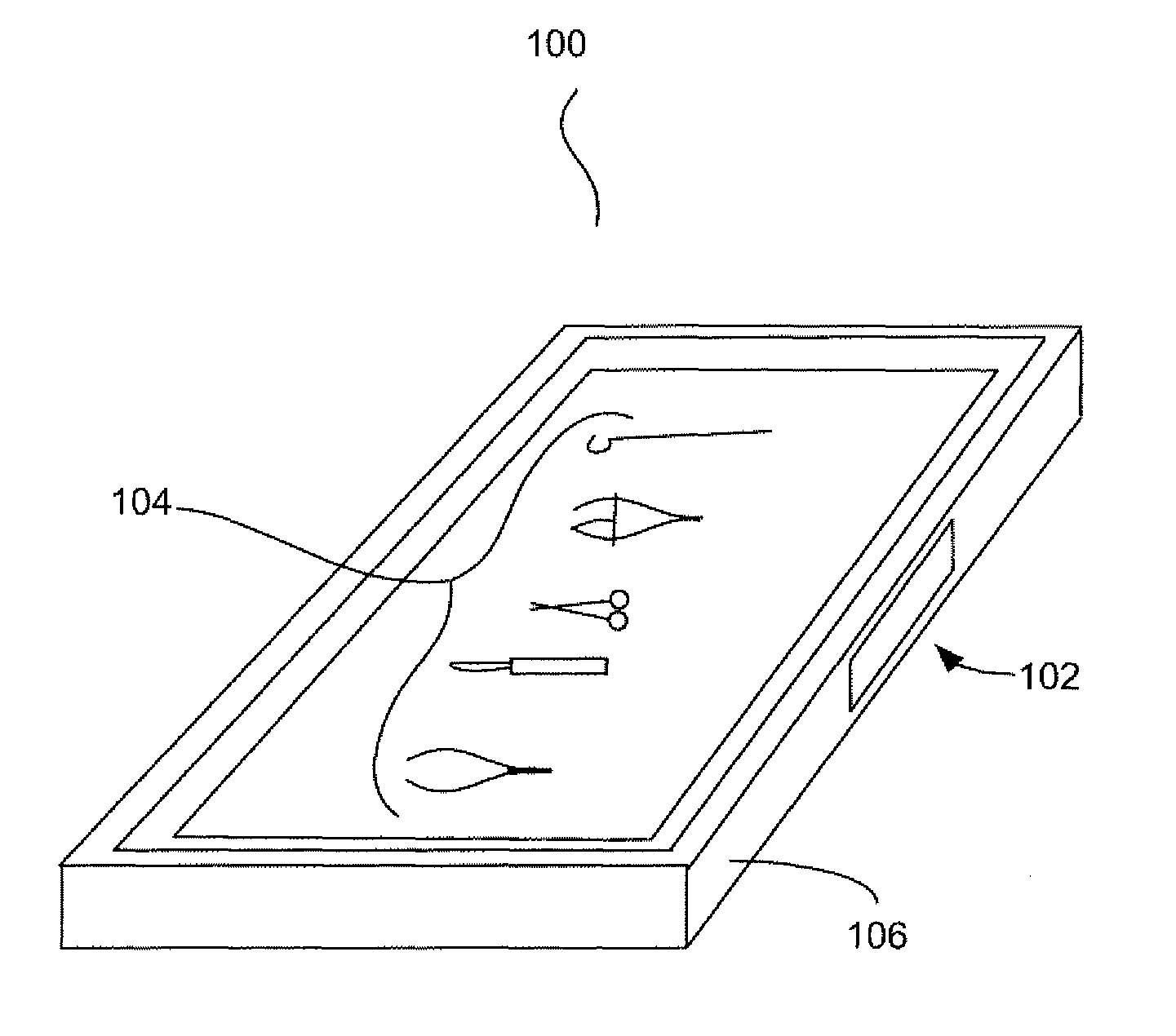
  • Insertable form factor for an instrument tray
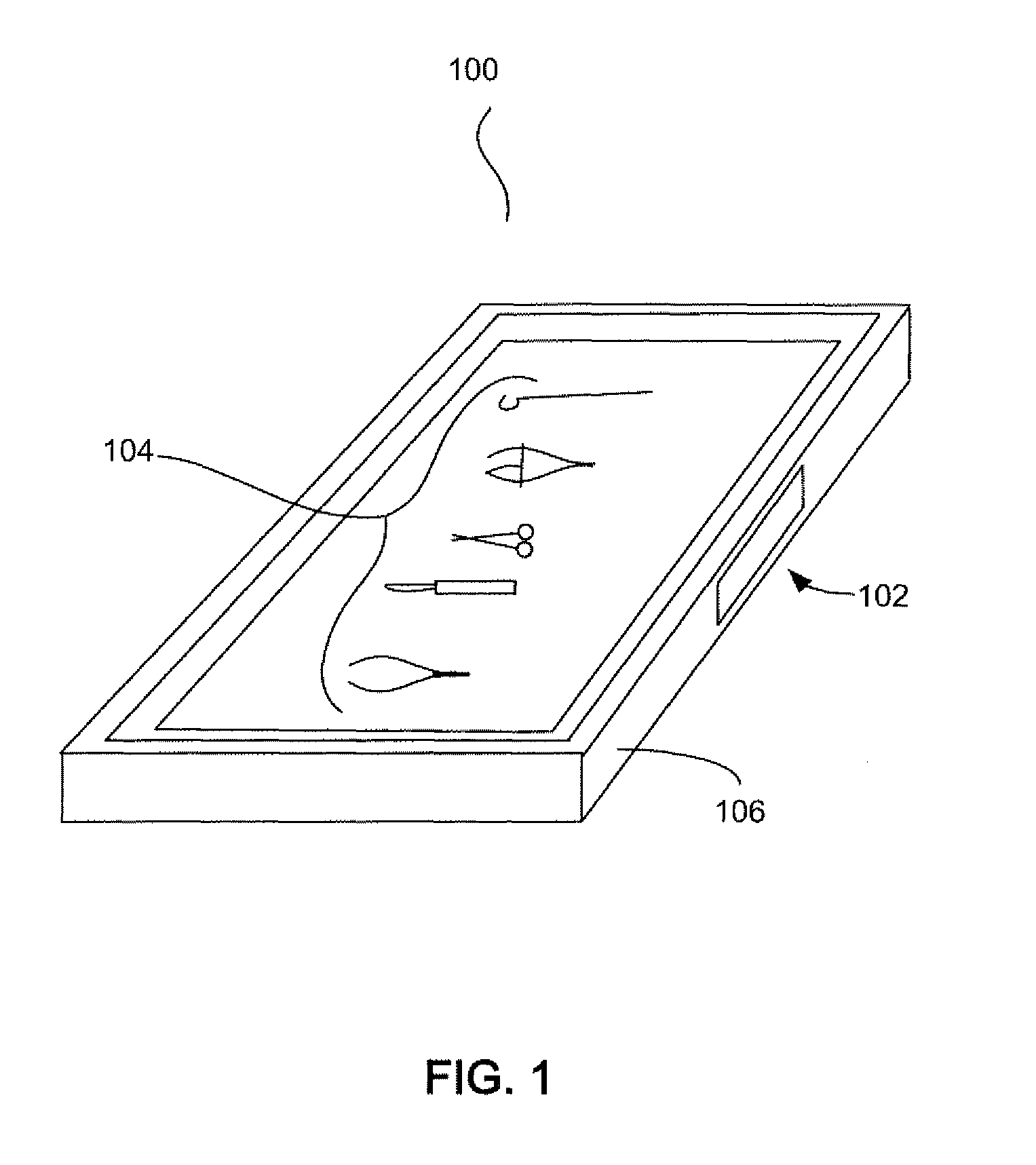
  • Insertable form factor for an instrument tray
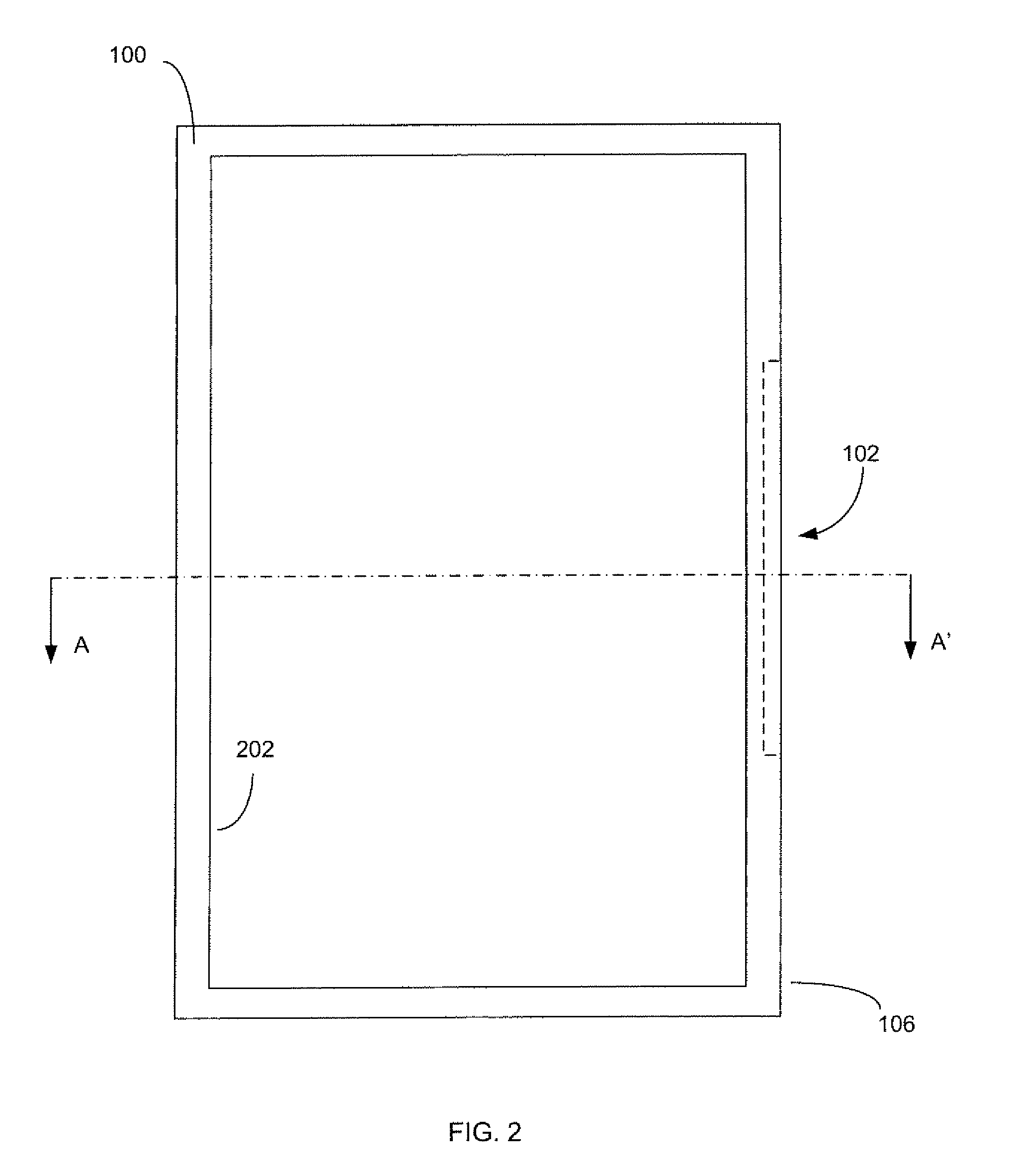
  • Insertable form factor for an instrument tray

Examples


Embodiment Construction

[0025]The following description is intended to convey a thorough understanding of the embodiments described herein by providing a number of specific exemplary embodiments and details involving trays, methods of manufacturing trays, and systems for tracking trays. It is understood, however, that the various embodiments are not limited to these specific embodiments and details, which are exemplary only. It is further understood that one possessing ordinary skill in the art, in light of known systems and methods, would appreciate the use of the exemplary embodiments for their intended purposes and benefits in any number of alternative embodiments, depending upon specific design and other needs.

[0026]The terminology used herein is for the purpose of describing particular embodiments only and is not intended to limit the scope of the present invention. As used throughout this disclosure, the singular forms “a,”“an,” and “the” include plural references unless the context clearly dictates ...


PUM


Abstract

An apparatus including a device having a slot formed on an exterior wall and a slot wall within the slot. A form factor may be insertable into the slot. The form factor also may include a transmitter embedded in the form factors wherein the transmitter is adapted to wirelessly communicate identification data.

Description

FIELD OF THE INVENTION[0001]Exemplary embodiments generally relate to instrument trays, and more particularly generally relate to identification of instrument trays.DESCRIPTION OF RELATED ART[0002]Surgical instrument storage and sterilization systems are known in the art. These systems, referred to as surgical instrument trays, surgical instrument kits, surgical trays, and / or surgical kits, typically consist of trays or boxes that hold a variety of general purpose and / or procedure specific surgical instruments, such as forceps, scissors, clamps, retractors, scalpels, etc. These surgical instrument trays are brought into the operating room (OR) when preparing for surgery, and also are used as a means to organize and store surgical instruments in a medical facility and even to transport instruments in and out of medical facilities.[0003]Due to advances in medical technology that have increased the number of surgical instruments now in use and due to the constant pressure in the health...

Claims


Application Information

Patent Timeline
Patent Type & Authority Patents(United States)
IPC IPC(8): G08B13/14
CPCG09B23/28
Inventor CAMBRE, CHRISTOPHERTETHRAKE, STEVEN M.VARNER, ROBERT
Owner WARSAW ORTHOPEDIC INC
Learn More