
Safety bypass gate for emergency exit from watering area to feeding area in livestock facility

a safety bypass and emergency exit technology, applied in the field of livestock management systems and methods, can solve problems such as animal injury or loss, block the normal flow, and increase the stress level of animals

Active Publication Date: 2011-06-28
OSBORNE INDS INC
View PDF22 Cites 3 Cited by
  • Summary
  • Abstract
  • Description
  • Claims
  • Application Information

AI Technical Summary

Benefits of technology

The safety bypass gate effectively reduces animal stress and prevents overcrowding in the watering area by providing an alternative passage during blockages, ensuring the animals' safety and well-being by automatically opening when normal passage is obstructed.

Problems solved by technology

Abnormal events can sometimes block the normal flow between the watering and feeding areas and raise the stress levels on the animals.
Under some abnormal circumstances, the water pen may become overpopulated or the animals may be blocked from the feeding or watering areas, leading to animal injury or loss.

Method used


Image

  • Safety bypass gate for emergency exit from watering area to feeding area in livestock facility
  • Safety bypass gate for emergency exit from watering area to feeding area in livestock facility
  • Safety bypass gate for emergency exit from watering area to feeding area in livestock facility

Examples


Embodiment Construction

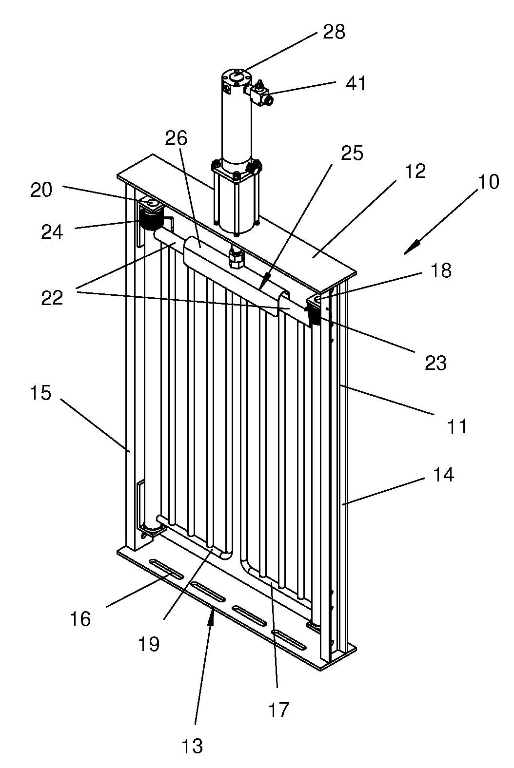
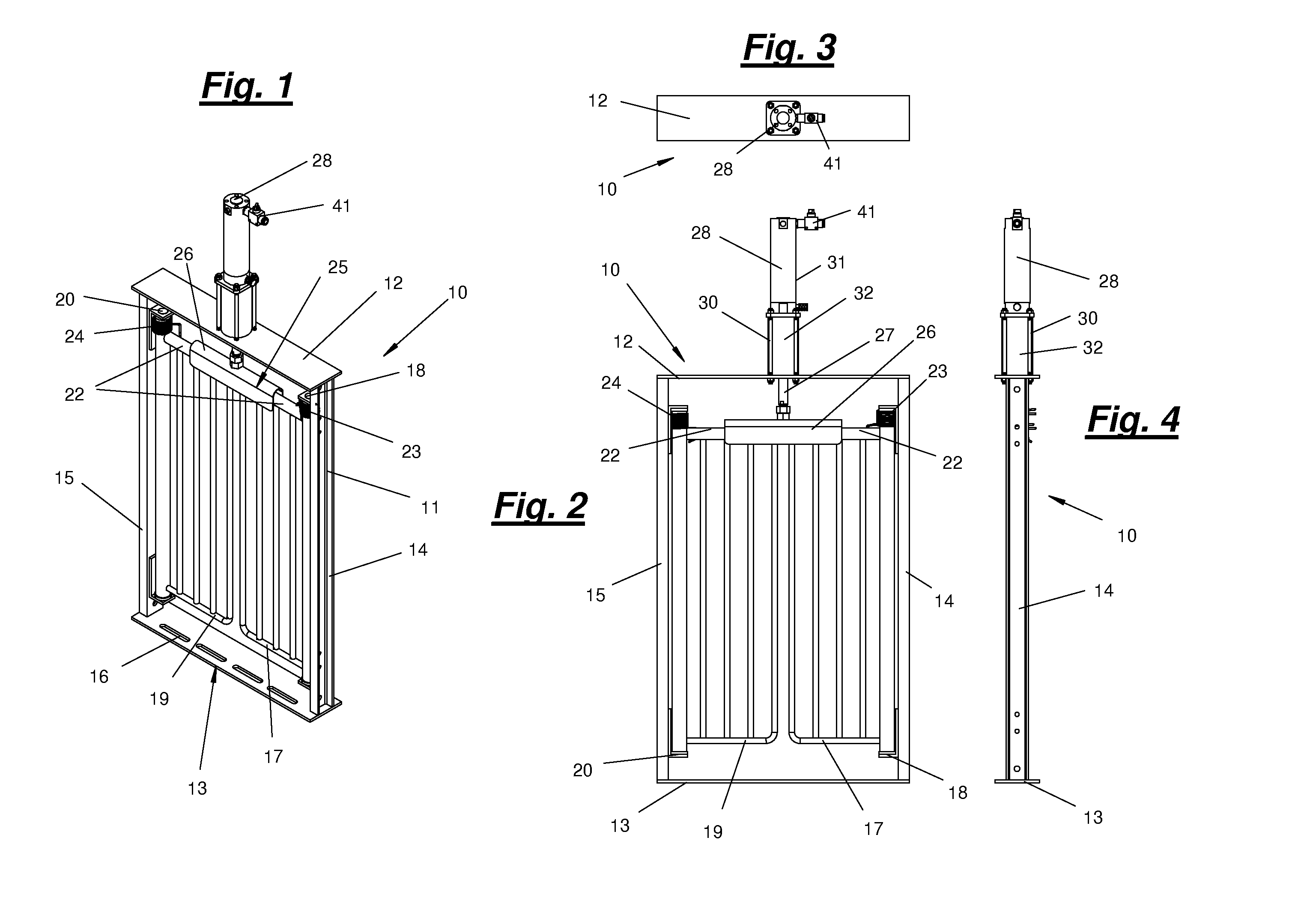
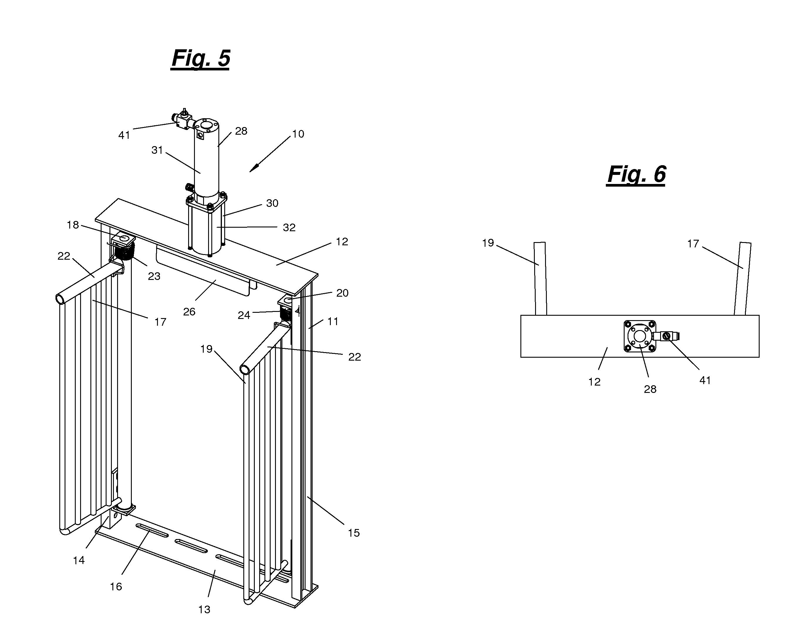
[0024]A safety bypass gate and livestock management system according to the present invention will now be described in detail with reference to FIGS. 1 to 10 of the accompanying drawings.

[0025]As shown in FIGS. 1 to 7, the safety bypass gate 10 includes a frame 11 comprising top and bottom frame members 12, 13, and right and left vertical side frame members 14, 15. Floor anchor holes 16 are provided in the bottom frame member 13 to secure the gate 10 to the floor of a pen in which it is used. The vertical side frame members 14, 15 can also be fastened to pen dividers, walls, or stationary posts to secure the bypass gate 10 in a desired location.

[0026]A first gate member 17 is mounted to the right side frame member 14 using a first hinge 18 for pivotal movement about a first vertical axis. A second gate member 19 is mounted to the left side frame member 15 using a second hinge 20 for pivotal movement about a second vertical axis. Bushings 21 can be used in the hinges 18, to ensure sm...


PUM


Abstract

A safety bypass gate is provided for use with a livestock management system having a sorting scale arranged between watering and feeding areas. The safety bypass gate changes from a closed position to an open position to provide an emergency exit from the watering area when a condition exists that prevents animals from passing over the sorting scale. The safety bypass gate includes a pair of pivoting gate members and a channel member that fits over the top edges of the gate members to secure them closed. The channel member is attached to a pneumatic actuator that uses air pressure to hold the channel member in its locked position, and a spring return that moves the channel member to its unlocked position upon a drop in air pressure. Springs bias the gate members from their closed positions to their open positions when the channel member moves to its unlocked position.

Description

RELATED APPLICATIONS[0001]This application claims the benefit under 35 U.S.C. 119(e) of U.S. Provisional Application No. 60 / 810,493 filed on Jun. 1, 2006.BACKGROUND OF THE INVENTION[0002]1. Field of the Invention[0003]The present invention relates to livestock management systems and methods in which animals are kept in a pen having a watering area separate from a feeding area, and in particular, to a safety bypass gate used to provide an emergency passage for animals upon occurrence of abnormal events that block a normal passage across a sorting scale between the watering and feeding areas.[0004]2. Description of the Related Art[0005]Split-weight feeding systems using automated sorting mechanisms are used in livestock facilities to improve feeding efficiencies, to limit the weight distribution spread of the animals in the herd, and to reduce sort losses at market. An example of a split-weight feeding system is described in U.S. Pat. No. 7,210,428. This split-weight feeding system re...

Claims


Application Information

Patent Timeline
Patent Type & Authority Patents(United States)
IPC IPC(8): A01K29/00
CPCA01K1/0023A01K1/0017
Inventor THIBAULT, RONALD M.
Owner OSBORNE INDS INC
Learn More