
Ejector blade system

a technology of ejector blades and blades, which is applied in the direction of transportation items, loading/unloading vehicle arrangment, and refuse collection, etc., can solve the problems of loss of stability, difficulty in moving with conventional dump trucks, and minimizing the loss of stability

Inactive Publication Date: 2011-07-19
HOLMES JAMES +1
View PDF25 Cites 12 Cited by
  • Summary
  • Abstract
  • Description
  • Claims
  • Application Information

AI Technical Summary

Benefits of technology

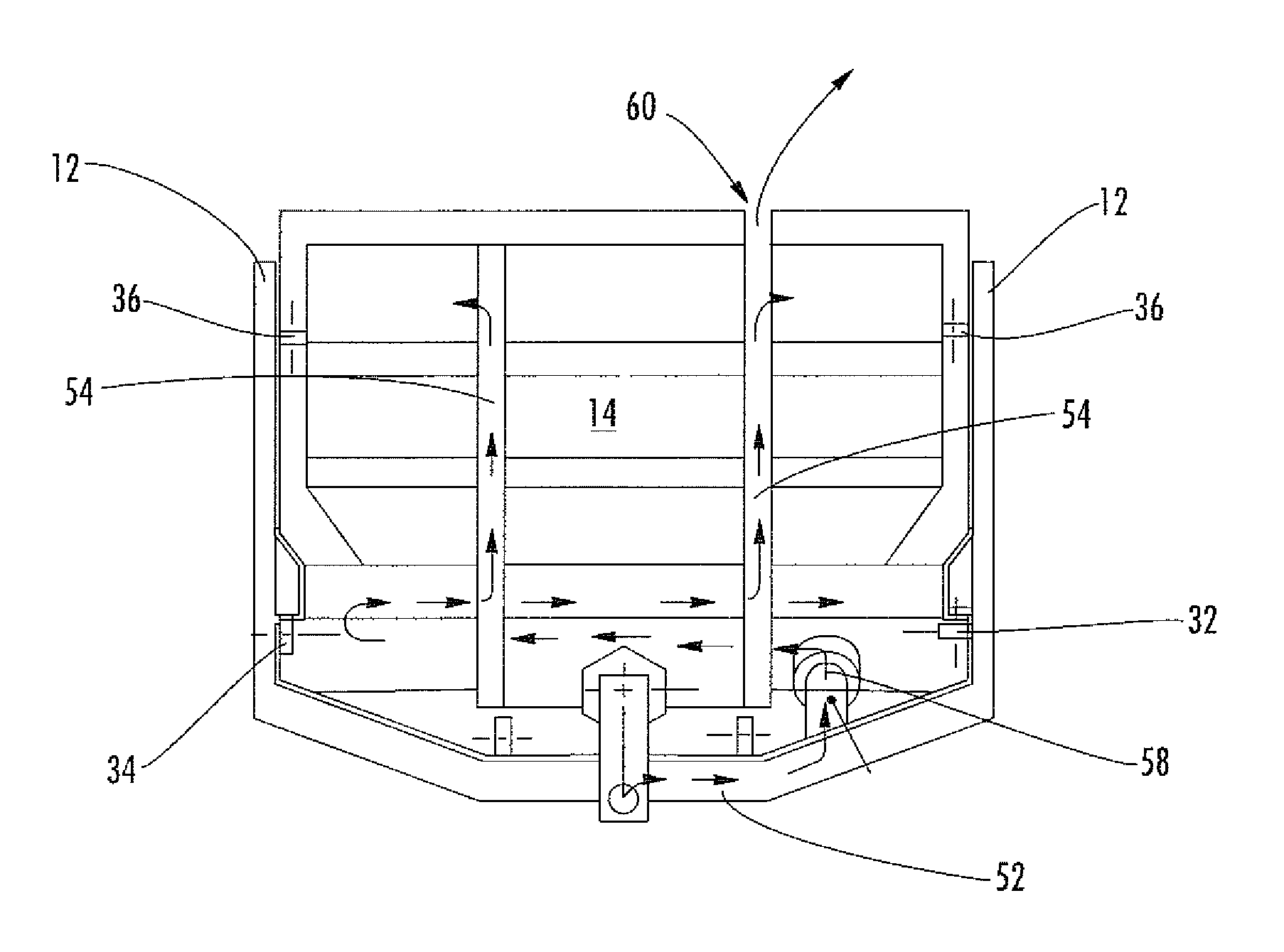
[0006]One aspect of the present invention relates to a device and method for combining a fluidly driven vibrator with an ejector blade of an ejector truck. When actuated, the vibrator vibrates thereby loosening material that has become adhered to the ejector blade. The ejector truck comprises a fluidly driven extension cylinder for extending and retracting the ejector blade. In one embodiment, fluid from the extension cylinder is used to power the vibrator. The fluid is directed from the extension cylinder through the vibrator motor to actuate the vibrator. After the fluid passes through the vibrator it is directed to a fluid accumulator. The accumulator has a volume that allows fluid to accumulate therein until the pressure inside the accumulator reaches a predetermined maximum amount. When the pressure reaches the predetermined maximum amount it no longer accepts additional fluid. When the ejector blade is retracted and fluid from the cylinder is returned to tank, the pressure that has built up within the accumulator forces the fluid out of the accumulator and through the vibrator in the reverse direction through the extension cylinder, thereby actuating the vibrator again, until pressure within the accumulator stabilizes to the preset level and volume. This use of an accumulator allows the vibrator to be actuated during both extension and retraction of the ejector blade without the need for a separate fluid return hose.
[0008]In another aspect of the invention, the ejector blade comprises a plurality of low friction guides to help guide the blade through the receptacle body and prevent the ejector blade from twisting laterally and pitching fore and aft about the longitudinal axis of the receptacle body. These guides may be rollers, self lubricating guide blocks, or any other suitable guide.

Problems solved by technology

Work machines are used in earth moving operations to move material, such as dirt, rock, clay, ash, and various other materials that can become sticky when they are wet making them difficult to move with conventional dump trucks.
A dump truck typically raises its receptacle body to dump the load which can result in loss of stability whereas the receptacle body of an ejector truck does not raise up as the load is ejected, thereby minimizing the loss of its stability.
Ejector trucks are useful in many applications where a traditional tilting dump truck is undesirable or impractical.
In contrast, some of the material in the receptacle body of regular dump trucks can get stuck or frozen to the sides and floor of the receptacle body.
Carry back builds up thereby making conventional dump trucks inefficient since they loose load capacity which adds to the cost of operations.
Although ejector blade machines do a good job of preventing carry back inside the receptacle body, material can still get stuck and continue to build up on the ejector blade itself, thereby creating a carry back situation.
However, this solution has not been successful due to crevices in the blade and scratches in the plastic from abrasive materials that enable material adhesion due to the high amount of pressure against the ejector blade as it ejects a load.
Although this design may work for traditional dump trucks, it does not work with trucks that have ejector blades because of the longitudinal movement of the ejector blade through the receptacle body.
It would be impractical and prone to failure to have hydraulic hoses or electric cables dangling or moving through the receptacle body as the ejector blade is extending and retracting through the length of the receptacle body.

Method used


Image

  • Ejector blade system
  • Ejector blade system
  • Ejector blade system

Examples


Embodiment Construction

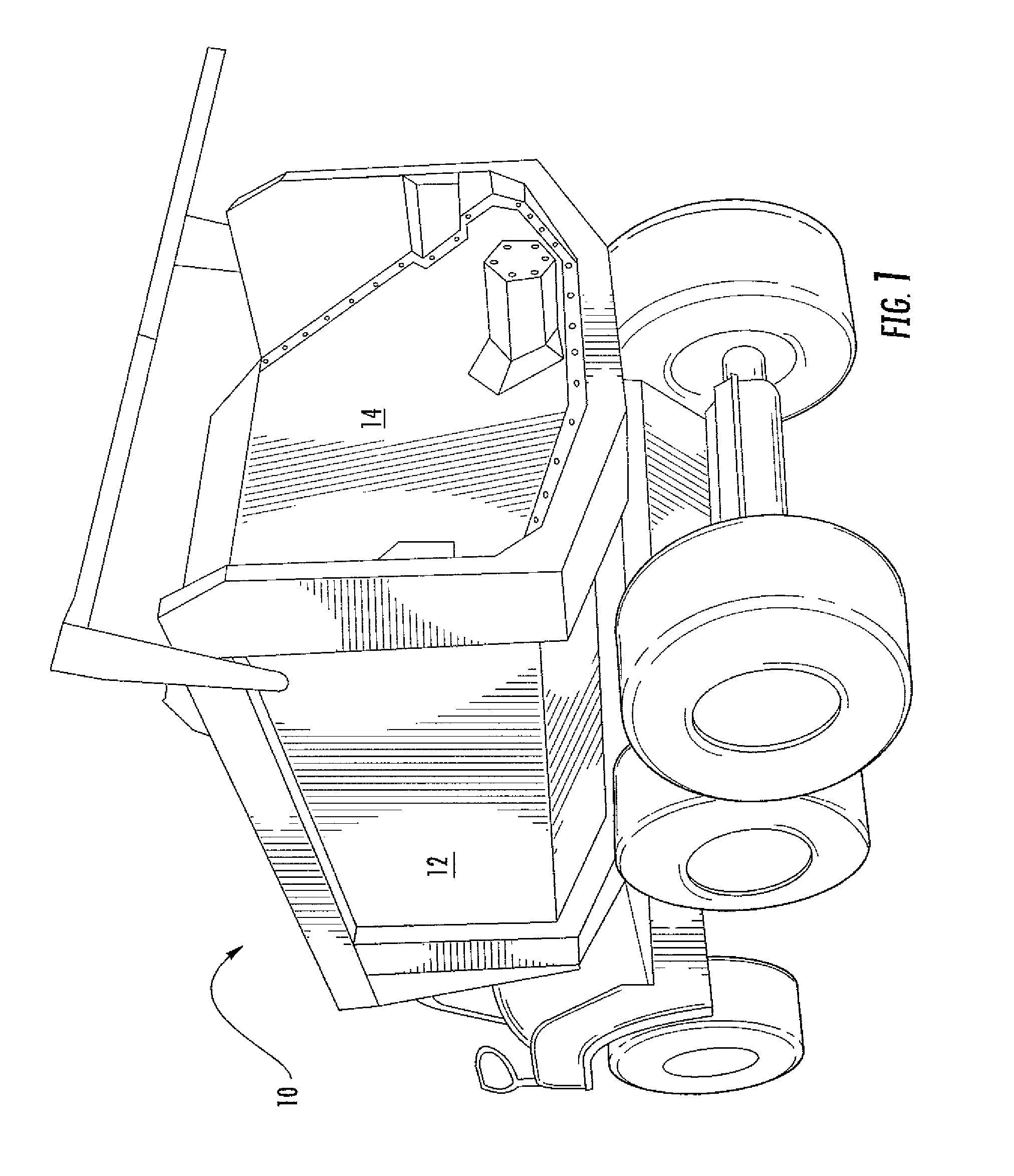
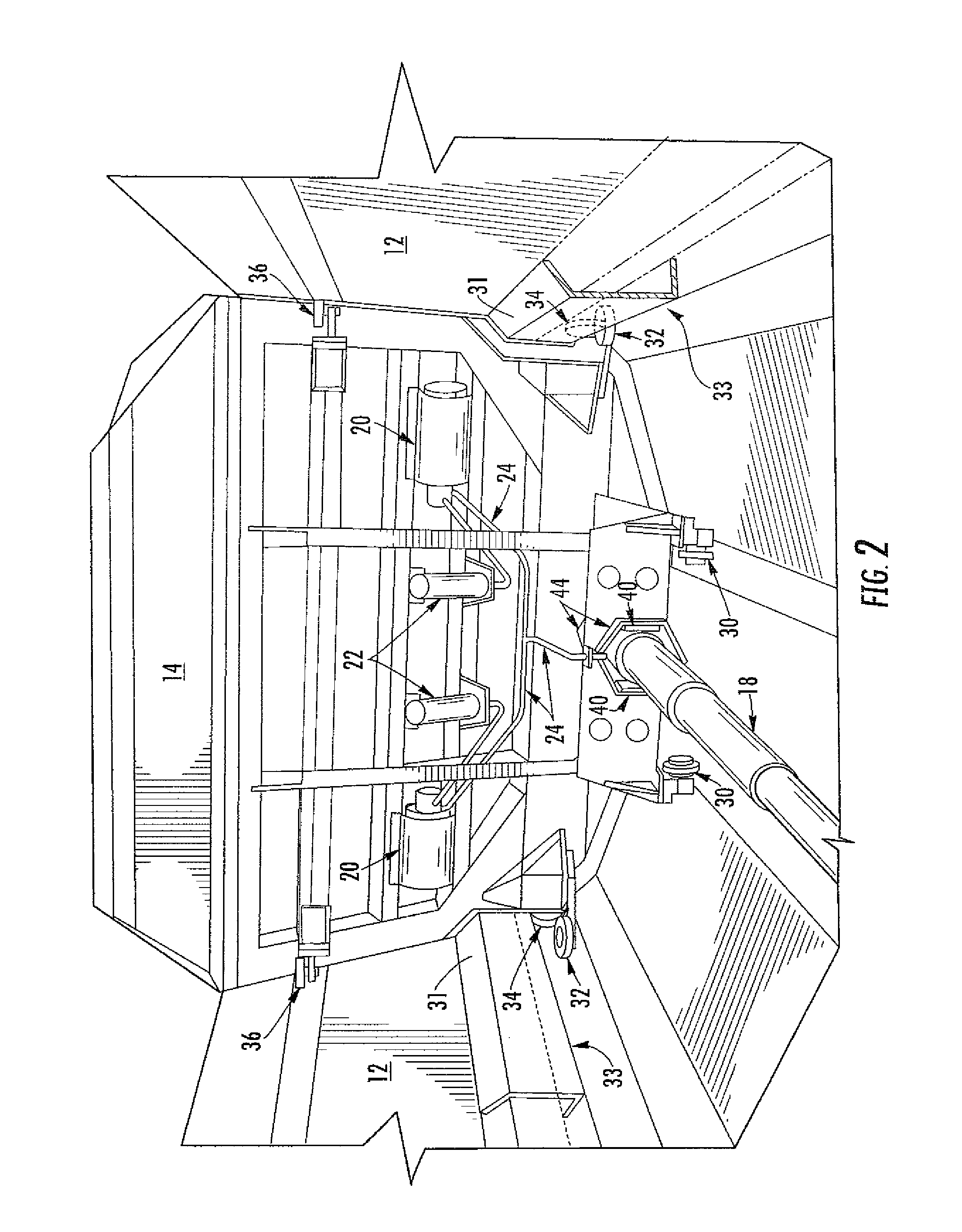
[0016]The present invention relates to an improved movable ejector 14 for an ejector truck 10. The movable ejector 14 will be referred to herein as the ejector blade 14, however, it should be noted that the movable ejector 14 may be any suitable shape. One aspect of the invention relates to a device and method for combining a fluidly driven vibrator 20 with an ejector blade 14. FIGS. 1 and 2 show different views of the ejector blade 14 in its extended position within the receptacle body 12 of the ejector truck 10. FIG. 2 shows two vibrators 20 combined with the backside of the ejector blade 14, however, any suitable number may be used. The vibrator 20 may be any suitable vibrator 20 including a rotational vibrator or hammer vibrator. In one embodiment, the vibrator 20 is comprised of eccentrically mounted weights located between two bearings. The weights are rotated by a fluid motor. When actuated by the flow of fluid through the vibrator 20, the vibrator 20 vibrates thereby looseni...


PUM


Abstract

An ejector blade adapted to be combined with an ejector truck or trailer body. In one embodiment, the blade comprises fluidly actuated vibrators for loosening material that has become adhered to the ejector blade. In another embodiment, the blade is heated to help prevent material from being frozen to the blade. In yet another embodiment, the blade comprises a plurality of low friction guides to aid the blade in moving through the receptacle body.

Description

BACKGROUND OF THE INVENTION[0001]Work machines are used in earth moving operations to move material, such as dirt, rock, clay, ash, and various other materials that can become sticky when they are wet making them difficult to move with conventional dump trucks. Two types of work machines that are commonly used in the industry to perform this task are dump trucks and ejector trucks. Both types of trucks have a receptacle body to carry the material being moved. A dump truck typically raises its receptacle body to dump the load which can result in loss of stability whereas the receptacle body of an ejector truck does not raise up as the load is ejected, thereby minimizing the loss of its stability. In an ejector truck, an ejector blade is moveably mounted within the receptacle body and is coupled to a hydraulic ram or cylinder or other mechanical means which extends and retracts to move the blade through the body. Ejector trucks are useful in many applications where a traditional tilti...

Claims


Application Information

Patent Timeline
IPC IPC(8): B60P1/00
CPCB60P1/006
Inventor HOLMES, JAMESPRILLINGER, PETER
Owner HOLMES JAMES
Learn More