Hot stick switch head

Active Publication Date: 2011-07-26
ROBERTSON KENNY D
View PDF32 Cites 8 Cited by
  • Summary
  • Abstract
  • Description
  • Claims
  • Application Information

AI Technical Summary

Problems solved by technology

Inevitably, there is an element of danger in working with these high voltages, yet there are many instances in which utility workers have to either service or repair these high voltage power lines in the performance of their duties.
Oftentimes these fuses have to be replaced during inclement weather conditions including heavy rains and high winds.
Many of these prior art switch heads, however, do not have a mean

Method used


Image

  • Hot stick switch head
  • Hot stick switch head
  • Hot stick switch head

Examples


Embodiment Construction

It should also be understood that the specific devices illustrated in the attached drawings, and described in the following specification, are simply exemplary embodiments of the inventive concepts defined in the appended claims. Hence, specific dimensions and other physical characteristics relating to the embodiments disclosed herein are not to be considered as limiting, unless the claims expressly state otherwise.

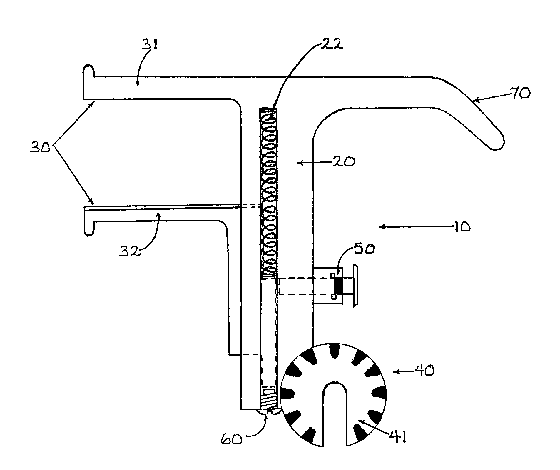
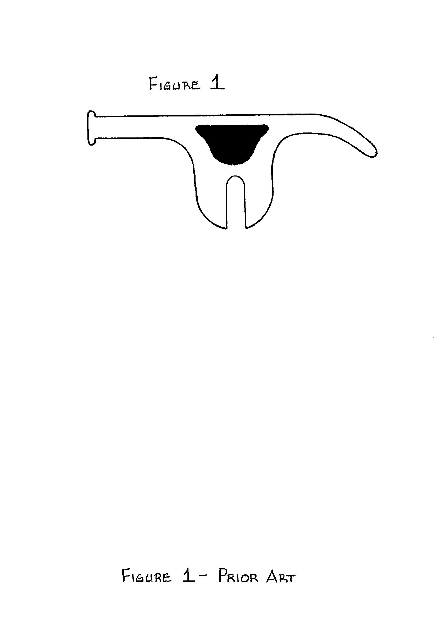
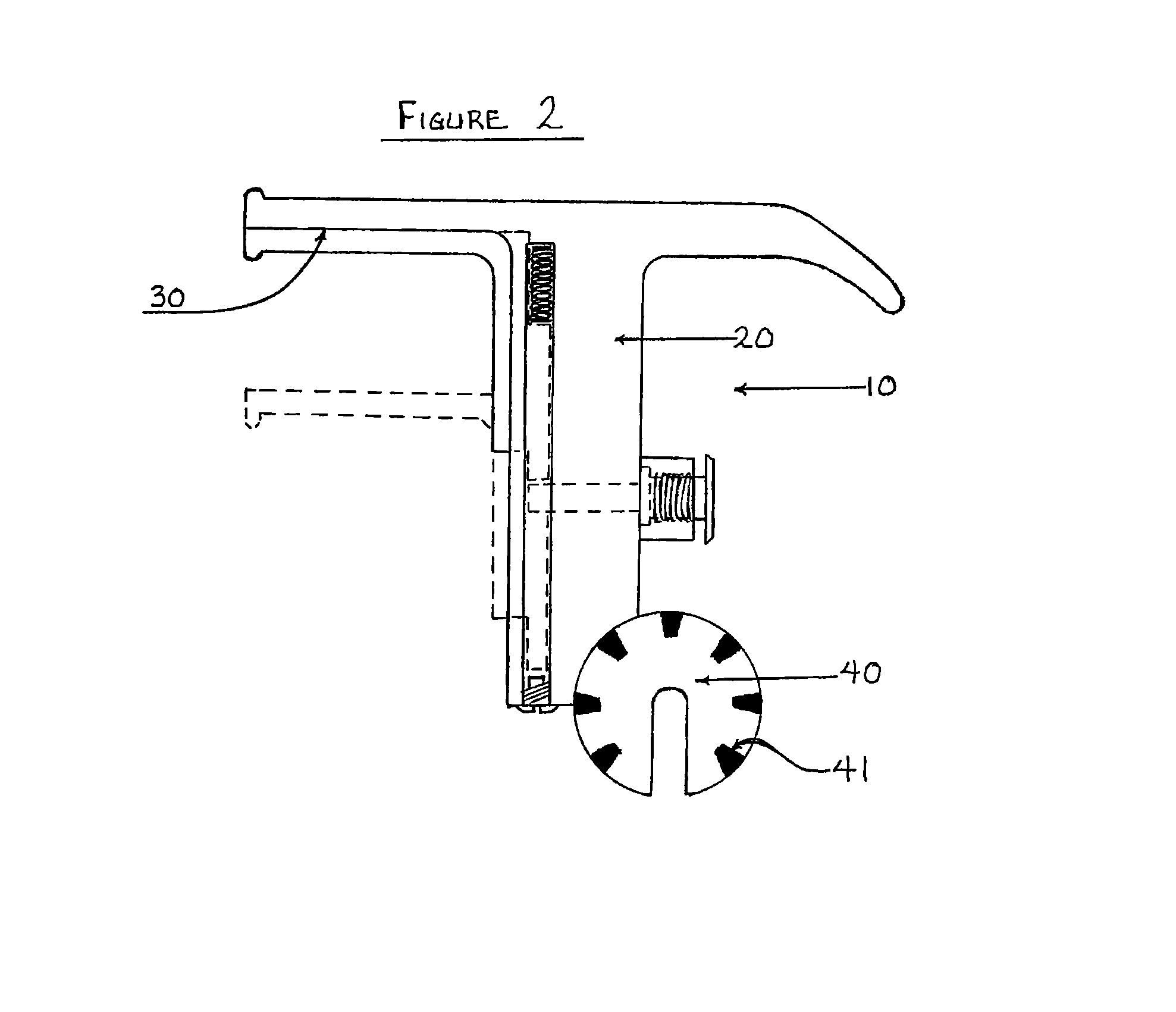
An embodiment disclosed herein provides a hot stick switch head capable of securing a fuse barrel assembly to the switch head while the fuse barrel assembly is being manipulated. FIG. 1 illustrates a prior art switch head configured with a single extension arm. Referring to an embodiment of the present invention as shown in FIG. 2, the hot stick switch head 10 has a body 20, a jaw assembly 30, and a base 40. The jaw assembly 30 is attached to the top end of the body 20, while the base 40 is attached to the bottom end of the body 20. The base 40 further comprises a swivel ...


PUM


Abstract

A hot stick switch head is described and shown in the specification and drawings having a body, a jaw assembly attached to the top end of the body, and a base attached to the bottom end of the body. The base is adapted to be attached to an insulated pole or “hot stick.” The body has a channel extending longitudinally along at least a portion of the body. The jaw assembly has an open position and a closed position for securing high-voltage fuses, fuse barrel assemblies, or other similar or related devices during removal and installation.

Description

I. BACKGROUNDA. Technical FieldAn embodiment disclosed herein is generally directed to a hot stick switch head for securing high-voltage fuses, fuse barrel assemblies, or other similar or related devices during removal and installation.B. Background ArtThe present invention relates to a tool used to remove and replace electrical fuses and / or other related devices commonly used in electrical transmission and distribution systems. As detailed in U.S. Pat. No. 6,725,745 to Palmieri, single-phase and three-phase electrical power is delivered to commercial, industrial, and residential users through a system known as the power distribution grid, which generally includes such components as generating plants, transformers, and electrical power lines. These lines generally consist of both transmission lines, which typically have AC voltages in the range of about 70,000 to about 750,000 volts, and distribution lines, which typically have AC voltages in the range of about 2,300 to about 50,000...

Claims


Application Information

Patent Timeline
IPC IPC(8): B25B27/14H01R11/12
CPCH02G1/02
Inventor ROBERTSON, KENNY D.
Owner ROBERTSON KENNY D
Why Eureka
Try Eureka