Multi-use torque fitting and compressible ferrule

a torque fitting and ferrule technology, applied in the direction of fluid pressure sealing joints, multi-purpose tools, sleeve/socket joints, etc., can solve the problems of failure to force the threaded body portion, etc., to prevent substantial fluid leakage, facilitate repetitive flexion of the lever, and degree of elasticity

Active Publication Date: 2011-07-26
DIBA IND
View PDF43 Cites 27 Cited by
  • Summary
  • Abstract
  • Description
  • Claims
  • Application Information

AI Technical Summary

Benefits of technology

[0005]The length of tubing is accommodated by the channel of the torque fitting. The compressible ferrule is applied to an end of the length of tubing such that the compressible ferrule is positioned to cooperate with the torque fitting to prevent substantial fluid leakage when the assembly is applied to a fluid-handling device.
[0006]In accordance with another embodiment of the present invention, threaded body portion comprises a compressing edge on the underside of the threaded body portion. One of the threaded body portion or the torque-limiting body portion of the fitting comprises a lever, while the other body portion comprises an abutment. The lever comprises a first arresting surface and a yielding surface, while the abutment comprises a second arresting surface and an engaging surface. The lever and the abutment are configured such that the yielding surface of the lever and the engaging surface of the abutment engage when torque below a threshold level is applied in rotating the torque-limiting body portion in a compressive direction of rotation. The lever and the abutment are further configured such that the engaging surface contacts the yielding surface and sufficiently deflects the lever to allow the lever to bypass the abutment when torque above the threshold level is applied in rotating the torque-limiting body portion in the compressive direction of rotation. This deflection of the lever by the abutment causes the lever to flex toward the body portion comprising the lever and away from the body portion comprising the abutment. The lever preferably is configured with a degree of elasticity sufficient to enable repetitive flexion of the lever. Meanwhile, the first and second arresting surfaces are configured to arrest relative rotation between the threaded body portion and the torque-limiting body portion when engaged. This engagement of the first and second arresting surfaces forces the threaded body portion to rotate with the torque-limiting body portion when torque is applied to the torque-limiting body portion in a decompressive direction of rotation. The length of tubing is accommodated by the channel of the torque fitting. The compressible ferrule is applied to an end of the length of tubing such that the compressible ferrule is positioned to cooperate with the torque fitting to prevent substantial fluid leakage when the assembly is applied to a fluid-handling device.

Problems solved by technology

Further, the threaded body portion and the torque-limiting body portion generally are configured such that when torque above the threshold level is applied to the torque-limiting body portion, rotation of the torque-limiting body portion in the compressive direction of rotation fails to force the threaded body portion to rotate with the torque-limiting body portion.

Method used


Image

  • Multi-use torque fitting and compressible ferrule
  • Multi-use torque fitting and compressible ferrule
  • Multi-use torque fitting and compressible ferrule

Examples


Embodiment Construction

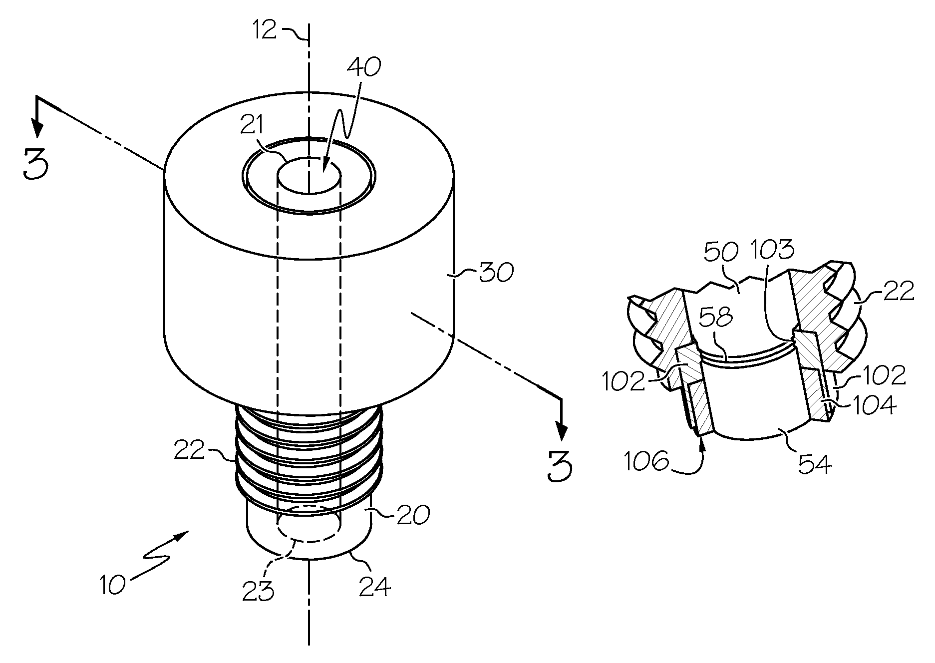
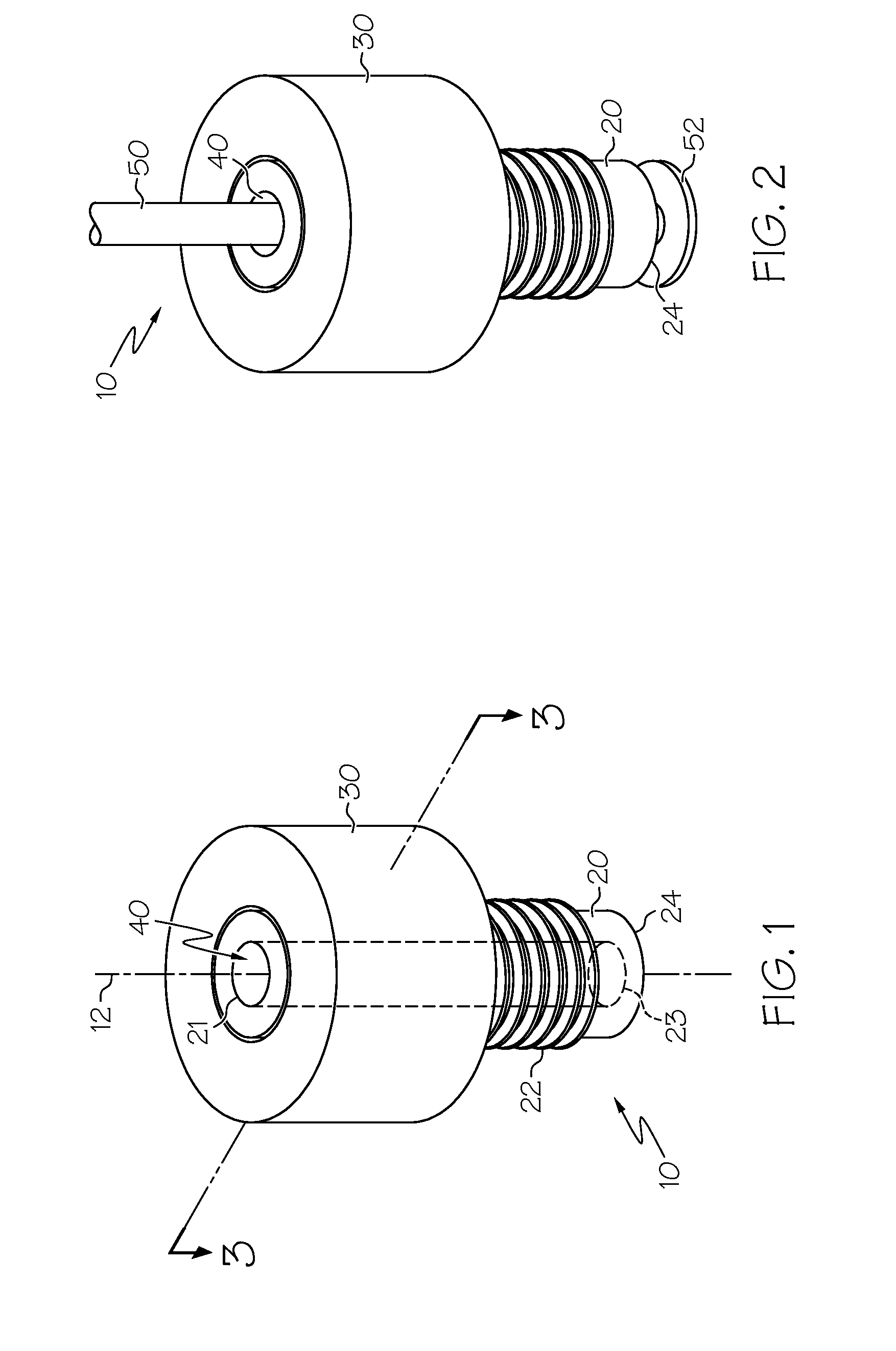
[0020]Generally, embodiments of the present invention relate to an assembly that comprises a torque fitting, a length of tubing, and a compressible ferrule. As shown in FIG. 10, the assembly 1 uses a torque fitting 10 and a compressible ferrule 80 to secure in a substantial leak-proof manner a length of tubing 50 to a port 122 of a fluid manifold, a fluid valve assembly, a fluid container, or other type of fluid-handling device 120. The compressible inverted cone ferrule 80 is shown in FIG. 10 for illustrative purposes only and it is contemplated that another compressible ferrule configured to secure in a substantial leak-proof manner a length of tubing 50 to a port 122 of a fluid-handling device 120 may replace the compressible inverted cone ferrule 80. Further, it is contemplated that, according to one embodiment, the assembly comprises a fluid-handling device comprising a port in addition to the fitting, the length of tubing, and the compressible ferrule. The compressible ferrule...


PUM


Abstract

An assembly comprises a multi-use torque fitting, a length of tubing, and a compressible ferrule, wherein the assembly is configured to couple an end of the length of tubing to a port of a fluid-handling device in a hermetically sealed or substantially leak-proof manner. Generally, the fitting is configured to provide a degree of compression to the compressible ferrule sufficient to prevent fluid leakage at the ferrule / port interface. This fitting generally comprises a threaded body portion and a torque-limiting body portion, wherein the threaded body portion and the torque-limiting body portion are arranged concentrically along a longitudinal axis of the fitting.

Description

BACKGROUND OF THE INVENTION[0001]Embodiments of the present invention generally relate to assemblies comprising a torque fitting, a length of tubing, and a compressible ferrule used to secure an end of the length of tubing to a port of a fluid manifold, a fluid valve assembly, a fluid container, or other type of fluid-handling device in a substantially leak-proof manner. Generally, the configuration of the fitting prevents over-tightening or over-compression of the compressible ferrule compressed between the fitting and the fluid-handling device to which the assembly is applied while ensuring sufficient compression of the ferrule between the fitting and the port of the fluid-handling device.BRIEF SUMMARY OF THE INVENTION[0002]In accordance with one embodiment of the present invention, the torque fitting comprises a threaded body portion, a torque-limiting body portion, and a channel. The threaded body portion and the torque-limiting body portion typically are arranged substantially ...

Claims


Application Information

Patent Timeline
Patent Type & Authority Patents(United States)
IPC IPC(8): F16L25/00
CPCF16L15/08F16L35/00Y10T16/39
Inventor HELSTERN, GARY C.
Owner DIBA IND
Why Eureka
Try Eureka