Forward-directed atherectomy catheter

a catheter and forward-directed technology, applied in the field of forward-directed atherectomy catheters, to achieve the effect of greater relative stretch for

Inactive Publication Date: 2006-10-12
SPARKS KURT D
View PDF15 Cites 161 Cited by
  • Summary
  • Abstract
  • Description
  • Claims
  • Application Information

AI Technical Summary

Benefits of technology

[0016] As previously described, the adventitia exhibits elastic type properties up to a point of maximum strain. Strain is defined as the degree of stretch or elongation of a material that is undergoing stress (force input). The elastic properties of the tunica adventitia allows the vessel wall to “stretch” over the outer surface of the distal housing, and more specifically allows the tunica adventitia to stretch across the struts of each open cell. As the tunica adventitia is stretched across the struts of each cell, the tunica adventitia becomes taught, and under ideal conditions the tunica adventitia will not be able to impinge or ingress into the cell or into the interior of the distal housing. However, in practice slight impingement of the tunica adventitia though the cells and inward past the imaginary boundary of the inner surface of the distal housing may occur. However, preventing or limiting the tunica adventitia from entering the interior of the distal housing (translating radially inward past the inner surface of the distal housing) is accomplished by adjusting the size, configuration and thickness of the distal housing. In a preferred embodiment, FIG. 5b shows one of the cells from a tangential perspective. This view demonstrates the “straight-line” pathway the tunica adventitia will assume when stretched over Strut A and Strut B. FIG. 5b demonstrates that if the tunica adventitia was stretched across Strut A and Strut B, it would not be able to enter into the interior of the distal housing. However, as mentioned earlier, at first the inner surface layer of the wall of the tunica adventitia may enter just inside the inner surface of the distal housing. However, as increased engagement force is used to advance the catheter into the vascular plaque, the tunica adventitia will experience even greater relative stretch force over the struts, which will serve to tighten the tunica adventitia over each cell, thereby making its potential ingress into the cell less likely.

Problems solved by technology

From a device or interventional perspective, chronic total occlusions differ from stenosed blood vessels in that catheter systems to treat them cannot be guided over a guide wire through the occlusion since no pathway yet exists through the occlusion.

Method used


Image

  • Forward-directed atherectomy catheter
  • Forward-directed atherectomy catheter
  • Forward-directed atherectomy catheter

Examples


embodiment 200

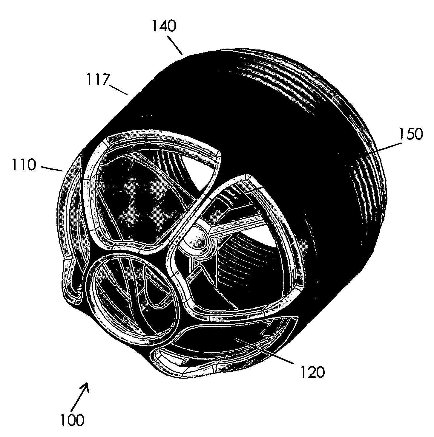
[0041]FIG. 4a shows a second preferred embodiment 200 of the catheter system. The main components consist of the distal housing assembly 210, the internal rotational cutter 220, the torqueable, flexible catheter shaft assembly 140, and the torqueable, flexible internal drive shaft 150.

[0042] A second preferred embodiment of the distal housing assembly 210 is shown in FIG. 4b. In the preferred embodiment shown in FIG. 4b, the distal housing assembly is comprised of two separate components for ease of manufacturing. The distal portion is the convex housing 211 and the proximal portion is the collar housing 217. The convex housing contains multiple openings or cells 212 separated by struts 213, an outer surface 214, an inner surface 215, and a proximal annular face 216. The edges of each strut are rounded so as to present an atraumatic surface when the struts are in contact with the vessel wall. Alternate embodiments 280 and 29 of the convex housing are shown in FIG. 4f and FIG. 4g res...

second embodiment

[0047] A preferred embodiment of the internal drive shaft 150 is shown in FIG. 4a and FIG. 4d. In this embodiment, the drive shaft is constructed of a single wound coil. The direction of the winding may be in either direction, but a preferred method may be to wind the coil clockwise (as looking proximal to distal along the drive shaft axis) if the internal cutter is to be rotated in a counter-clockwise direction. In this way, the rotational force upon the drive shaft will serve to “tighten” the coil in its wound configuration. In a second embodiment, the drive shaft may be fabricated from a layered coil configuration similar to that described for the catheter shaft, however instead of three layered coils only two are used. This configuration is referred to as a “Bi-Plex” and is utilized for greater flexibility, however torque transmission is afforded generally in one rotational direction only. If the direction of the internal cutter is again rotated in a counter-clockwise direction,...

embodiment 300

[0050]FIG. 9 shows a preferred embodiment 300 of the catheter system that employs the fluid-propelling element 160, and also shows the distal housing 211, the collar housing 217, the internal cutter 220, the catheter shaft 140, and the internal drive shaft 150. As vascular plaque material is shaved within the distal housing 211 it will become suspended within the infused saline solution and the fluid-propelling component 160 will serve to quickly remove this fluid suspension from the interior of the distal housing 120 and into the annular space between the catheter shaft 140 and the drive shaft 150. Referring to the preferred embodiment in FIG. 8, if the fluid-propelling component 160 is rotated counter-clockwise in a continuous fashion, as viewed proximal to distal along the catheter central axis, fluid within the distal housing will be urged to flow in a proximal direction within the annular space between the drive shaft 150, and the inner surface of the catheter shaft 140. Altern...


PUM


Abstract

A catheter system is described for operation within a stenosed blood vessel. The catheter system includes a catheter shaft having at least one lumen. The catheter system further includes a convex distal housing that includes a series of openings along a convex surface that allow vascular plaque tissue to enter the interior of the distal housing. The catheter system also includes an internal rotational cutter having blades that are in proximity to the portion of the inner surface of the distal housing that includes the openings. Additionally, the catheter system includes a drive shaft coupled to the internal rotational cutter.

Description

FIELD OF THE INVENTION [0001] This invention applies to the field of interventional cardiology and interventional radiology, and more specifically to describe interventional (catheter) based systems designed to establish patent pathways through vascular chronic total occlusions (CTOs) and to debulk, or remove diseased tissue, or commonly referred to as plaque from stenosed coronary and peripheral arteries and veins. BACKGROUND OF THE INVENTION [0002] Cardiovascular and peripheral artery disease are routinely treated with interventional (catheter based) methods wherein balloon angioplasty and stenting re-establish patent blood flow to a vessel that has undergone the gradual atherosclerotic process in which plaque deposits have accumulated to narrow the lumen through the blood vessel. Angioplasty and stenting are well accepted amongst interventional physicians, and the long-term outcomes are clinically acceptable. Alternatively, surgery may be employed for those patients who are not s...

Claims


Application Information

Patent Timeline
Patent Type & Authority Applications(United States)
IPC IPC(8): A61B17/22
CPCA61B17/320758A61B2017/320775A61B17/320783
Inventor SPARKS, KURT D.
Owner SPARKS KURT D
Why Eureka
Try Eureka