Rotary electric machine and electric vehicle

a technology of electric motors and electric vehicles, which is applied in the direction of electric devices, propulsion by batteries/cells, magnetic circuit shapes/forms/construction, etc., can solve the problems of noise or vibration of motor torque, inability to appropriately reduce inherent cogging torque, and deterioration of ride quality, so as to achieve the effect of reducing the torque pulsation in relation to the stator current supplied to the stator winding

Active Publication Date: 2009-09-10
HITACHI ASTEMO LTD
View PDF13 Cites 89 Cited by
  • Summary
  • Abstract
  • Description
  • Claims
  • Application Information

AI Technical Summary

Benefits of technology

[0079]The reduction of torque pulsation has been described in the above-mentioned paragraphs of the effect of the invention and the problems to be solved by the invention. The reduction of torque pulsation performed by the following embodiments will be described specifically below. The embodiments to be described later can respectively reduce the cogging torque and the torque pulsation due to the stator current.
[0080]In a structure having a permanent magnet embedded in a rotary core, a magnetic flux density in the direction of rotation of a gap between a rotor and a stator tends to drastically change at an end of the permanent magnet in the rotation direction (which can also be described as “an end in the circumferential direction”), which may cause cogging torque. In the following embodiments, a magnetic air gap 257 is provided at an end of the permanent magnet corresponding to an end of a rotor magnetic pole (field pole) formed by the permanent magnet. The magnetic air gap 257 can reduce a drastic change in magnetic flux density of a gap between the above rotor and stator in the rotation direction. The magnetic air gap 257 can have an effect of decreasing the cogging torque.(2) Reduction of Pulsation Due to Stator Current
[0081]In the following embodiments, a magnetic air gap 258 is formed in an auxiliary magnetic pole (auxiliary salient pole 259) for forming a magnetic circuit on the q axis. The positions of the magnetic air gaps 258 are changed in the rotation direction as viewed along the direction of a rotary shaft. Such an arrangement can reduce the pulsation due to the stator current.(3) Reduction of Pulsation Due to Stator Current by Structure Having Little Influence on Cogging Torque
[0082]The conventional technique of reducing the torque pulsation has influences on both the cogging torque and the pulsation due to the stator current. When the cogging torque is intended to be reduced, the effect of reducing the pulsation due to the stator current becomes insufficient, or too sufficient. Thus, it is necessary to find out such conditions that can reduce both torque pulsations by repeating experiments. That is, even when an optimal condition for reducing the pulsation due to the stator current is found out, the condition is not always preferable for reduction of the cogging torque, and may be undesired one in many cases. Thus, it is very difficult to find a condition that can reduce both torque pulsations. Even if the preferable condition is found out, the condition tends to change depending on various factors. Every time a new rotary electric machine is designed, the experiment needs to be repeated. The solving means described in the above paragraph (2) has very little influence on the cogging torque. When a condition for reduction of the pulsation due to the stator current is adjusted, the adjustment cannot deteriorate the state of the cogging torque. This reduces the torque pulsation very easily.(Improvement of Efficiency of Rotary Electric Machine)
[0083]In the embodiment to be described below, the length of a magnetic bridge can be increased, which can reduce a leakage magnetic flux of the permanent magnet, leading to improvement of the efficiency of the rotary electric motor. The magnetic bridges can, be formed along the magnetic air gaps 257 or slots 282 provided on both ends of the field pole, thereby preventing the concentration of stress, resulting in a decreased sectional area of the magnetic flux, which leads to improvement of the efficiency.(Improvement of Productivity)
[0084]The external appearance of the rotary electric machine in an embodiment to be described later can be produced by punching using a silicon steel plate. Thus, the embodiment has excellent productivity. A core 301 has the shape symmetric with respect to that of the core 302 as will be described later. One silicon steel plate subjected to punching can be turned upside down to be used as the other core. As a result, the number of types of cores to be produced can be decreased to improve the productivity.

Problems solved by technology

Torque pulsation of the motor causes noise or vibration.
In particular, the torque pulsation on the low-speed side of the electric vehicle disadvantageously deteriorates ride quality.
When the concept of this method is intended to be further applied so as to reduce the torque pulsation due to the stator current, the inherent cogging torque cannot be appropriately reduced.
This makes it difficult to easily solve both pulsations.

Method used


Image

  • Rotary electric machine and electric vehicle
  • Rotary electric machine and electric vehicle
  • Rotary electric machine and electric vehicle

Examples


first embodiment

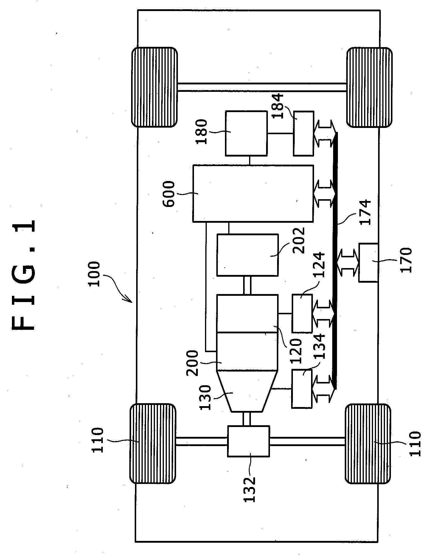
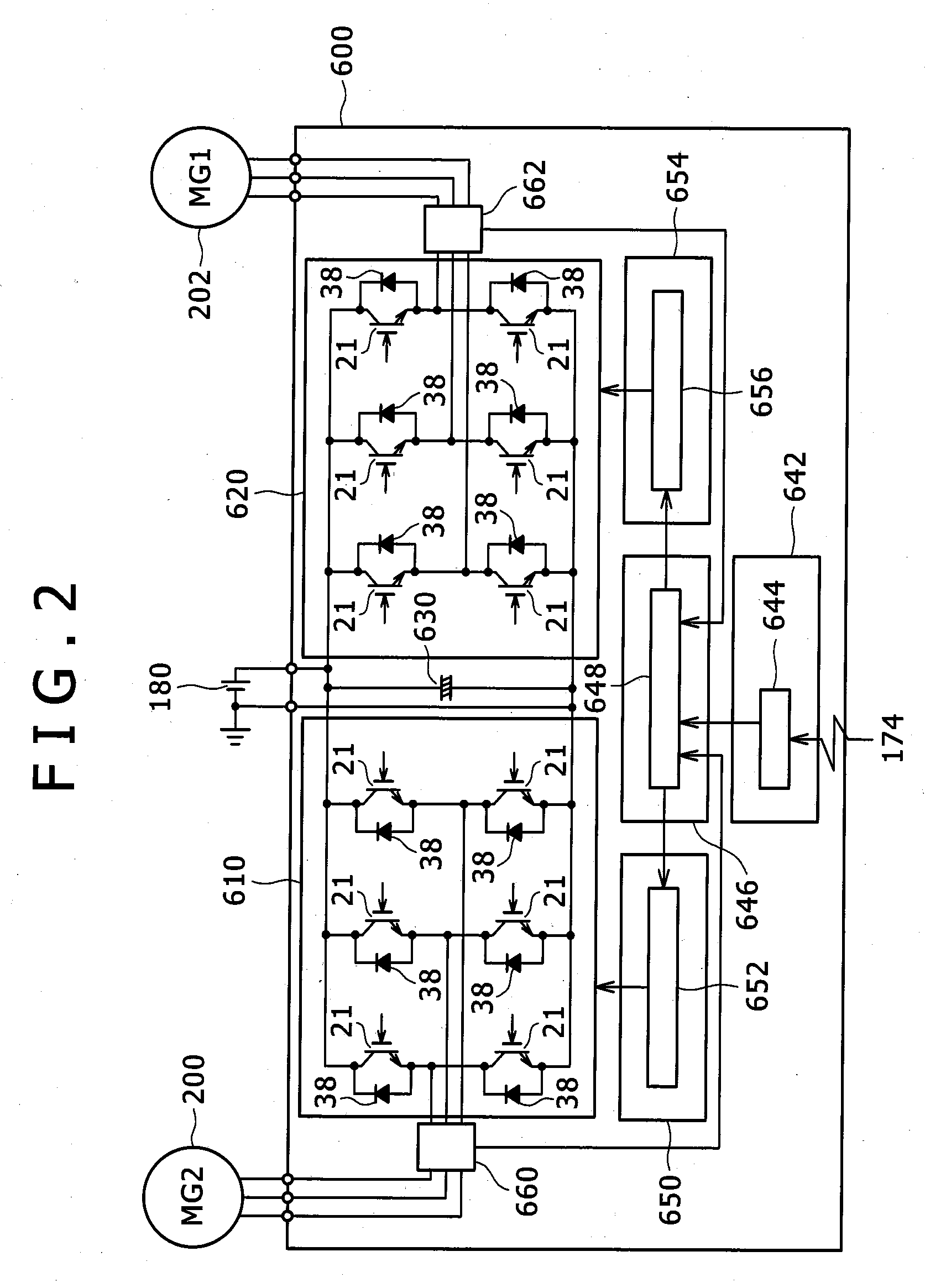
[0087]FIG. 1 is a diagram showing a schematic construction of a hybrid electric vehicle equipped with the rotary electric machine according to one embodiment of the invention. A vehicle 100 is equipped with an engine 120, a first rotary electric machine 200, a second rotary electric machine 202, and a battery 180. The battery 180 supplies direct-current power to a power converter (inverter) 600 for driving the rotary electric machines 200 and 202 when driving forces for the machines 200 and 202 are necessary. The power converter 600 converts the direct-current power into alternating-current power, and respectively supplies the converted alternating-current power to the rotary electric machines 200 and 202. In regeneration traveling, the rotary electric machines 200 and 202 generate alternating-current power based on kinetic energy of the vehicle to supply the power to the power converter 600. The power converter 600 converts the alternating-current power into direct-current power to...

second embodiment

[0157]FIGS. 22 to 24 are diagrams for explaining the second embodiment of the invention.

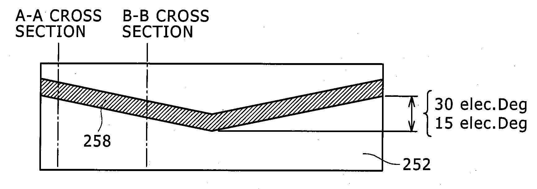
[0158]FIG. 22A is a sectional view of the rotor 250 corresponding to the section taken along the line A-A shown in FIG. 6A, and FIG. 22B is a sectional view of the rotor 250 corresponding to the section taken along the line B-B shown in FIG. 6B. That is, also in the second embodiment, the rotor core 252 is constructed of three cores as shown in FIG. 5. FIG. 22A shows the section of the core 301, and the FIG. 22B shows the section of the core 302. In the above example shown in FIG. 6, the magnetic air gaps 258 are formed as the slot on the surface of the rotor core 252. In the second embodiment, the air gaps 258 are formed inside the rotor core 252.

[0159]The sectional shape of the permanent magnets 245 (254a, 254b) is rectangular, and the magnetic air gap 258 is provided so as to be in contact with one side of the field pole made by the permanent magnets 245 (254a, 254b). In FIG. 22A, a magnetic a...

third embodiment

[0167]FIG. 25 shows a rotor 250 according to a third embodiment. FIG. 25A is a sectional view corresponding to the sectional view taken along the line A-A shown in FIG. 6A, and FIG. 25B is a sectional view corresponding to the sectional view taken along the line B-B shown in FIG. 6B. In the example shown in FIG. 25, two kinds of magnetic air gaps per one pole are provided. That is, a pair of magnetic air gaps 251 are also provided in the core on the outer peripheral side of the magnet, in addition to the magnetic air gaps 258 in the auxiliary salient pole 259. The magnetic air gaps 251 are symmetrically provided with respect to the d axis passing through the center of the permanent magnet. The magnetic air gaps 251 may be provided asymmetrically. The magnetic air gap 251 is mainly provided for reducing the cogging torque, and thus is disposed in the core on the outer peripheral side of the magnet through which the magnet flux passes. Such an arrangement can respectively reduce the p...


PUM


Abstract

A rotary electric machine includes a stator having stator windings; and a rotor rotatably disposed in the stator, said rotor having a rotor core provided with a plurality of magnets and a plurality of magnetic auxiliary salient poles formed between poles of the magnets. In this rotary electric machine: a magnetic air gap is provided in an axial direction of the rotor in a position shifted in a circumferential direction from a q axis passing through a center of the magnetic auxiliary salient pole within the magnetic auxiliary salient pole; and an amount of shifting the magnetic air gap from the q axis in the circumferential direction differs according to a position of the magnetic air gap in the axial direction so as to cancel torque pulsation in energization caused due to the magnetic air gap.

Description

BACKGROUND OF THE INVENTION[0001]1. Field of the Invention[0002]The present invention relates to a rotary electric machine, and an electric vehicle including the same.[0003]2. Description of the Related Art[0004]Drive motors used for electric vehicles or hybrid vehicles are required to output large power. Thus, permanent magnet type motors using a sintered magnet made of rare earth material for holding large energy is generally used. An embedded magnet type motor among the permanent magnet type motors is used as the drive motor which can satisfy requirements, including low-speed and large-torque output, and a wide range of rotation speeds.[0005]Torque pulsation of the motor causes noise or vibration. In particular, the torque pulsation on the low-speed side of the electric vehicle disadvantageously deteriorates ride quality. In a conventional motor, a permanent magnet is generally skewed so as to reduce cogging torque. Instead of skewing the permanent magnet, JP-A-2005-176424 has pr...

Claims


Application Information

Patent Timeline
Patent Type & Authority Applications(United States)
IPC IPC(8): H02K21/16
CPCH02K1/276B60L2270/145B60L1/02B60L3/0061B60L7/14B60L11/123B60L11/14B60L15/007B60L15/20B60L15/2009B60L2210/40B60L2240/36B60L2240/421B60L2240/423B60L2270/142Y02T10/641B60L50/16B60L50/61Y02T10/62Y02T10/64Y02T10/70Y02T10/7072Y02T10/72
Inventor HINO, NORIAKIMATSUNOBU, YUTAKASUGIMOTO, SHINJIKAMIYA, AKINORI
Owner HITACHI ASTEMO LTD
Why Eureka
Try Eureka