Gas turbine burner

Active Publication Date: 2010-07-15
ANSALDO ENERGIA SWITZERLAND AG
View PDF4 Cites 22 Cited by
  • Summary
  • Abstract
  • Description
  • Claims
  • Application Information

AI Technical Summary

Benefits of technology

[0087]In fact, the oil droplets, as soon as they are injected, are dragged away by the very high vorticity and turbulence and are distributed in an annular region close to the walls of the swirl chamber and mixing tube; therefore there is no risk that the oil droplets that contain small perce

Problems solved by technology

Nevertheless, for some reasons, such as interruptions of the gas service or gaseous fuel compressor problems, the gas may not be available for feeding the gas turbines.
Thus auto ignition (with consequent combustion in an ambient poor of air) would cause high NOx emissions.
Water to be mixed with the liquid fuel must be previously purified and demineralised; this requires adapted plants and substantially involves high costs, in particular in regions (such as the Gulf region) where

Method used


Image

  • Gas turbine burner
  • Gas turbine burner
  • Gas turbine burner

Examples


Embodiment Construction

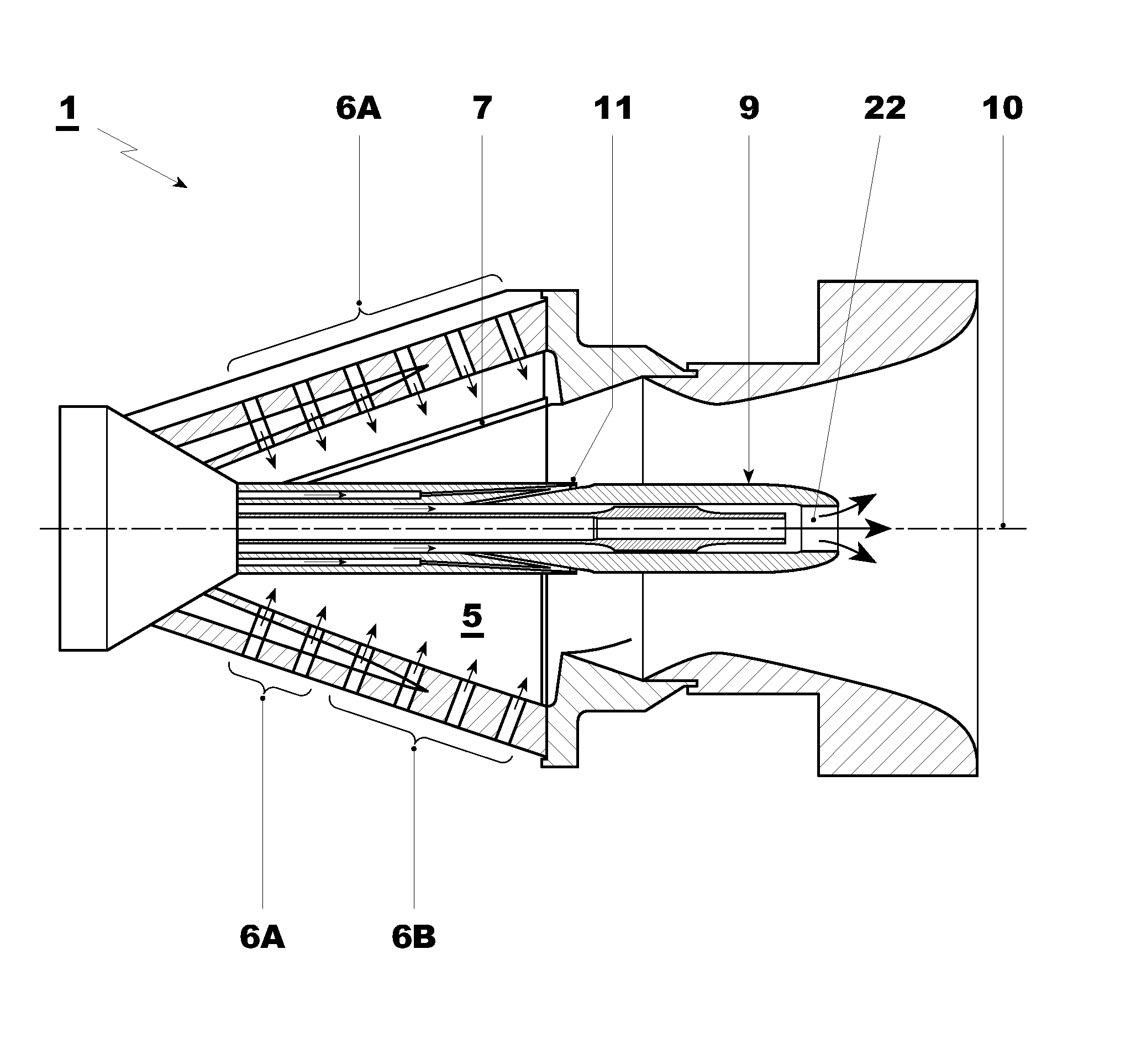
[0034]With particular reference to FIG. 8, the figure shows a burner of a gas turbine overall indicate by the reference 1; this burner is the first burner of a sequential gas turbine.

[0035]The burner 1 includes a swirl generator 2 and downstream of it a mixing tube 3.

[0036]The swirl generator 2 is defined by at least two conical walls facing one another to define a substantially conical swirl chamber 5.

[0037]Moreover, the walls of the swirl generator 2 are provided with nozzles 6 arranged to inject a gaseous fuel and apertures 7 arranged to feed an oxidizer (typically compressed air coming from the compressor) into the swirl chamber 5.

[0038]The burner 1 also includes a lance 9 which extends along a longitudinal axis 10 of the swirl generator 1 and is of retractable type, i.e. it may be removed without the need of disassembling the swirl generator for replacement or maintenance.

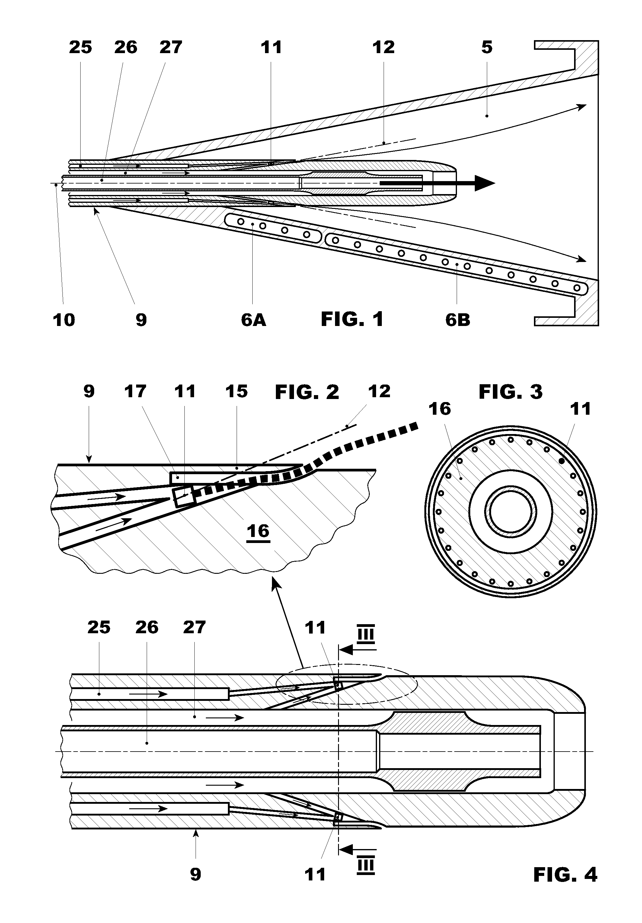
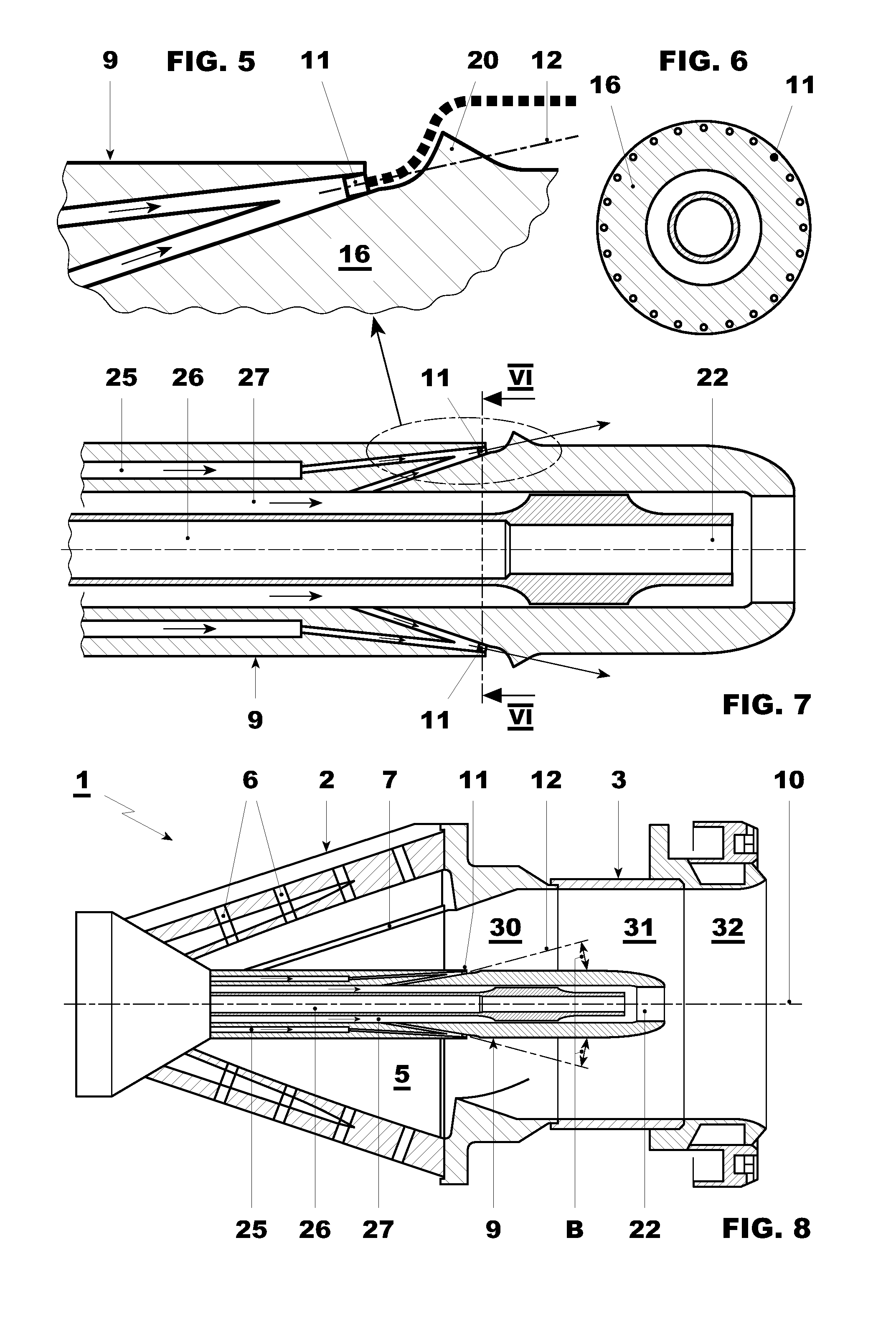
[0039]The lance 9 is provided with side nozzles 11 for ejecting a liquid or gaseous fuel within the burner....


PUM


Abstract

The burner (1) of a gas turbine includes a swirl generator (2) and, downstream of it, a mixing tube (3). The swirl generator (2) is defined by at least two walls facing one another to define a conical swirl chamber (5) and is provided with nozzles (6) arranged to inject a fuel and apertures (7) arranged to feed an oxidiser into the swirl chamber (5). The burner (1) includes a lance (9) which extends along a longitudinal axis of the swirl generator (2) and is provided with side nozzles (11) for ejecting a fuel within the burner (1). The side nozzles (11) have their axes (12) inclined with respect to the axis of the lance (9) and can be positioned along the axis of the burner.

Description

[0001]This application claims priority under 35 U.S.C. §119 to European application no. 09150601.4, filed 15 Jan. 2009, the entirety of which is incorporated by reference herein.BACKGROUND[0002]1. Field of Endeavor[0003]The present invention relates to a burner of a gas turbine; the invention also refers to a method for operating such a burner.[0004]2. Brief Description of the Related Art[0005]In particular, the present invention relates to a sequential combustion gas turbine, which includes a compressor for compressing a main air flow, a first burner for mixing a first fuel with the main air flow and generating a first mixture which is then combusted, a high pressure turbine where the combusted gasses are expanded, a second burner where a second fuel is injected into the gasses already expanded in the high pressure turbine to generate a second mixture which is then combusted, and a low pressure turbine where also these combusted gasses are expanded and are then discharged.[0006]Spe...

Claims


Application Information

Patent Timeline
IPC IPC(8): F02C7/22
CPCF23R3/34F23C6/047F23C2900/07002F23C2900/07021F23D11/105F23D11/12F23D11/402F23D14/58F23D14/64F23D17/002F23D2900/00015F23D2900/11101F23R3/12F23R3/286F23R3/343F23R3/346F23R3/36F23R2900/03341
Inventor EROGLU, ADNAN
Owner ANSALDO ENERGIA SWITZERLAND AG
Why Eureka
Try Eureka