Clamping device in main shaft driving device for machine tool

a technology of driving device and main shaft, which is applied in the direction of manufacturing tools, mechanical equipment, chucks, etc., can solve the problems of pulsation in the rotation state of the main shaft, the deviation of the rotational state of the dd motor resulting from the control, and the inability to follow the deviation of the dd motor, etc., to achieve good surface roughness of finished surface, reduce pulsation, and increase the rigidity of the main shaft without increasing the size o

Inactive Publication Date: 2010-05-20
TSUDAKOMA KOGYO KK
View PDF4 Cites 25 Cited by
  • Summary
  • Abstract
  • Description
  • Claims
  • Application Information

AI Technical Summary

Benefits of technology

[0012]Accordingly, it is an object of the present invention to provide a structure in the aforementioned main shaft driving device, in which pulsation in a rotation state of the main shaft driving device is reduced when a finishing operation is performed while continuously rotating a workpiece, and in which rigidity of the main shaft is increased even if a bearing is not made large.
[0020]According to the second aspect of the present invention, the clamping device includes a spring member that urges the clamp piston in a first direction, which is the same as a direction in which the braking portion causes the press-contact force to act upon the main shaft, the spring member causing a spring force to act upon the pressure-receiving surface, the spring force causing the press-contact force that causes the main shaft to be set in a partially clamped state to act upon the main shaft by the braking portion; the clamp piston has a first pressure-receiving surface and a second pressure-receiving surface, the first pressure-receiving surface extending in a second direction that is orthogonal to the first direction and receiving pressure of an operating fluid in the first direction, the first pressure-receiving surface receiving the spring force of the spring member, the second pressure-receiving surface extending in the second direction and receiving pressure of an operating fluid in a direction opposite to the first direction; and the operating fluid supplying mechanism includes a switching portion that selectively supplies the corresponding operating fluid from a common operating fluid supply source to at least one of the first and second pressure chambers, the first pressure chamber being formed by the first pressure-receiving surface and the frame, the second pressure chamber being formed by the second pressure-receiving surface and the frame. By virtue of this structure, a press-contact force that sets the main shaft in the normally partially clamped state acts upon the main shaft. By causing the pressure of the operating fluid to act upon the second pressure-receiving surface, it is possible to cause the main shaft to be set in the unclamped state, in which the clamp piston is displaced towards the second direction against the spring force of the spring member so that a press-contact force does not act upon the main shaft. In addition, by causing the pressure of the operating fluid to act upon the first pressure-receiving surface, the clamp piston is urged towards the first direction by the pressure of the operating fluid as well as by the spring force of the spring member, so that the main shaft can be in the completely clamped state. In this way, according to the second invention, the partially clamped state, the completely clamped state, and the unclamped state can be easily realized by only selectively switching the supply of operating fluid without adjusting the pressure of the operating fluid.
[0021]In addition, if a finishing operation is performed on a workpiece while continuously rotating the workpiece by the main shaft driving device when the main shaft is in the partially clamped state, variations in load that the main shaft driving device receives from the cutter that processes the workpiece can be restricted by rotational resistance. This makes it possible to reduce pulsation in the control of the DD motor and pulsation within a gear backlash range, so that the rotational state of the main shaft driving device can be made stabilized to a uniform state.
[0022]Further, since the clamping device provides rigidity to the main shaft in the main shaft driving device, it is possible to increase the rigidity of the main shaft without increasing the size of the bearing. As a result, it is possible to provide good surface roughness of a finished surface of the workpiece. In addition, it is possible to use a workpiece that is larger than a related workpiece using a bearing of the same diameter. Accordingly, since a bearing having a small diameter can be used, a high processing precision can be realized, and manufacturing costs of the main shaft driving device for a machine tool can be reduced.

Problems solved by technology

However, due to the variations in the load received from the cutter, the rotation of the DD motor resulting from the control may not be able to follow the deviation.
Therefore, the rotation of the DD motor is not necessarily uniform, and may include pulsation.
In addition, when a speed reducer including gears is used as the driving means of the main shaft, the rotation state of the main shaft may include pulsation in a backlash range of the gears due to the influence of the variations in load that is received from the cutter.
As a result, pulsation occurs in the rotation state of the main shaft driving device, thereby deteriorating surface roughness of a finished surface of the workpiece.
However, in order to withstand the large compression, the bearings themselves need to be large.
In addition, since the larger the diameters of the bearings, the higher the cost, manufacturing cost of the device is increased.

Method used


Image

  • Clamping device in main shaft driving device for machine tool
  • Clamping device in main shaft driving device for machine tool
  • Clamping device in main shaft driving device for machine tool

Examples


Embodiment Construction

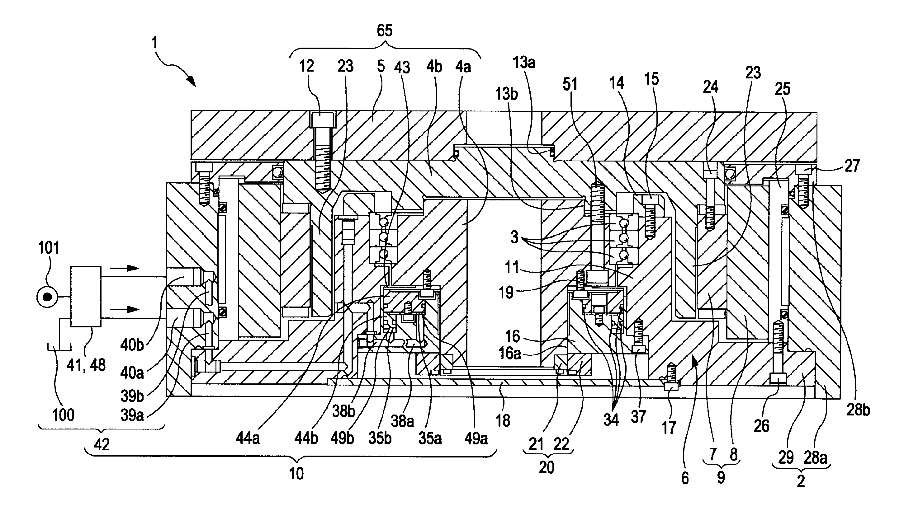
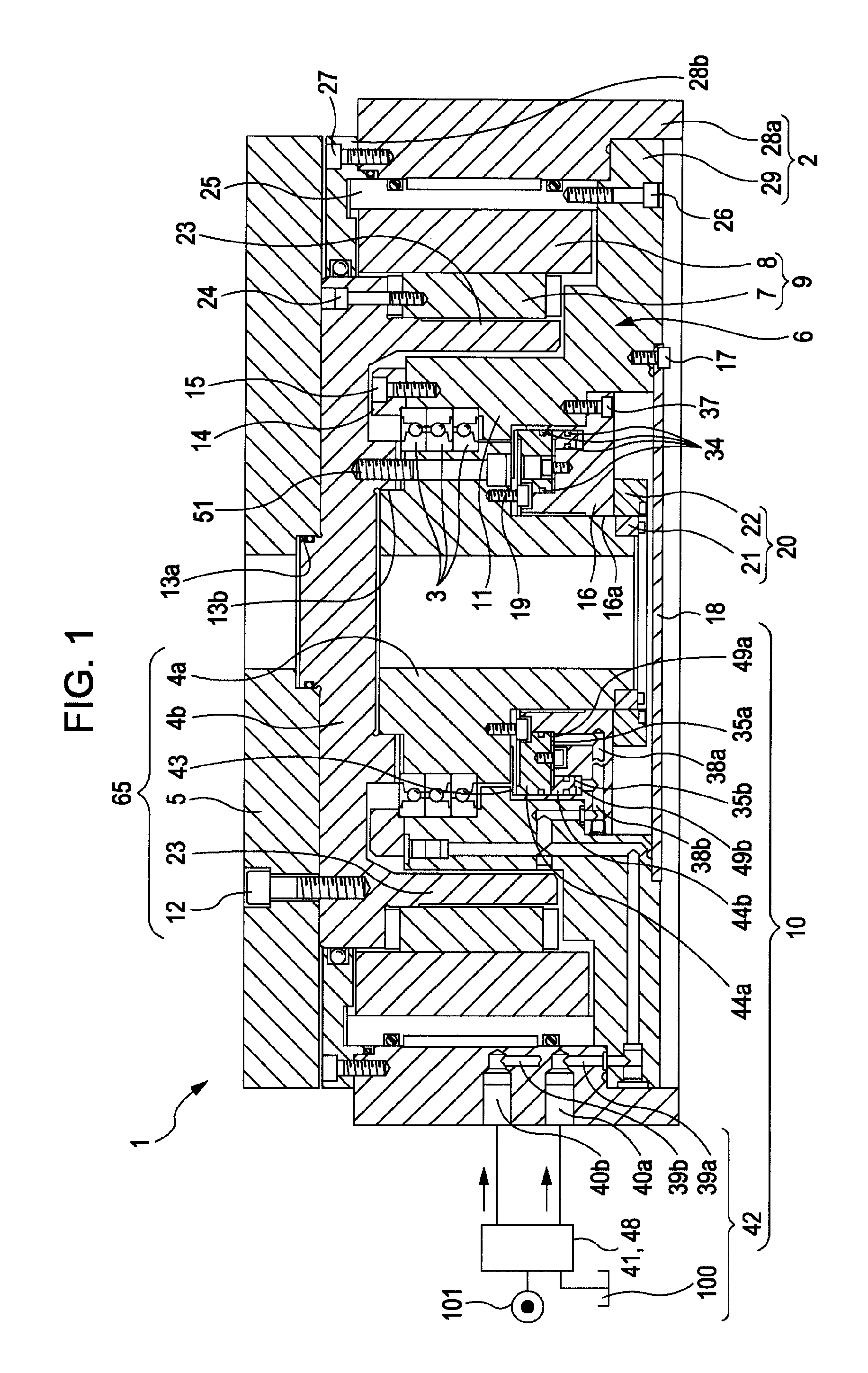
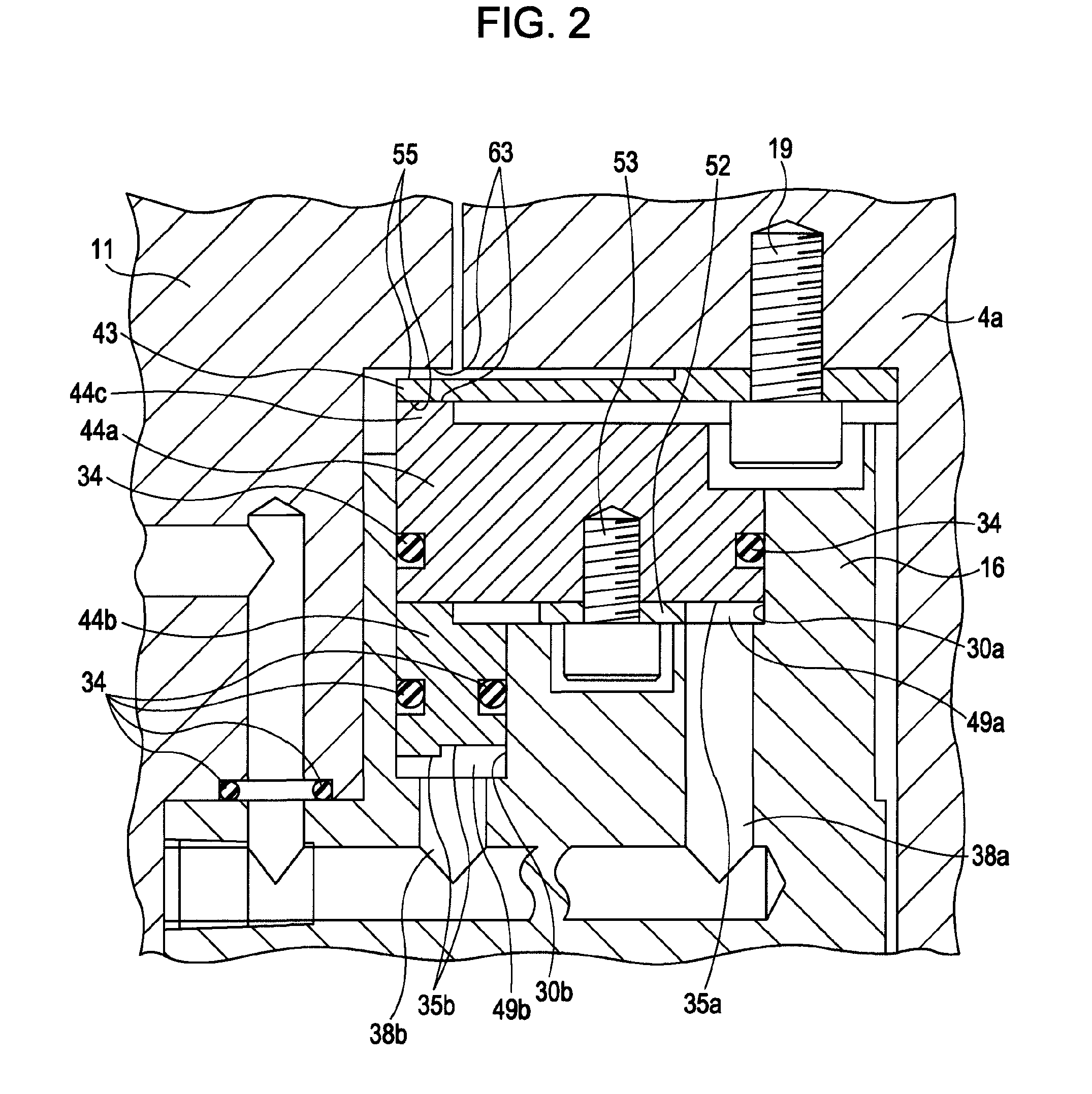
[0032]FIGS. 1 and 2 each show a rotation indexing table device 1 serving as a main shaft driving device for a machine tool according to the present invention. FIG. 1 is a general view thereof. In the description below, “axial direction” refers to an axial direction of a main shaft 4a that supports a circular table 5 serving as a member that is rotationally driven, and “radial direction” refers to a radial direction of the circular table 5 and the main shaft 4a, which are concentrically disposed.

[0033]In FIG. 1, the rotation indexing table device 1 includes a main shaft 4a, which is rotatably supported by a frame 2 and which has the member that is rotationally driven secured to one end thereof; a driving device 6 for rotationally driving the main shaft 4a; and a clamping device 10, which maintains an indexed rotational angle of the main shaft 4a. The frame 2 is such that a portion serving as a surface for setting to the machine tool is a flat surface. The frame 2 is provided with a c...


PUM

PropertyMeasurementUnit
pressureaaaaaaaaaa
press-contact forcesaaaaaaaaaa
pressuresaaaaaaaaaa

Abstract

A clamping device in a main shaft driving device for a machine tool, in which the main shaft driving device rotationally driving a main shaft by a driving device, the clamping device includes: a braking member provided at a side of the frame and including a pressure-receiving surface and a braking portion; a pressure chamber formed by the pressure-receiving surface and the frame; and an operating fluid supplying mechanism provided for supplying the operating fluid from an operating fluid supply source to the pressure chamber. The press-contact force is caused to act upon the main shaft. The operating fluid supplying mechanism includes a switching portion that selectively supplies the operating fluid. The braking member is formed so that the braking portion causes the press-contact forces that differ from each other.

Description

BACKGROUND OF THE INVENTION[0001]1. Field of the Invention[0002]The present invention relates to a clamping device in a main shaft driving device for a machine tool. More particularly, the present invention relates to a clamping device in a machine-tool main shaft driving device that rotationally drives by a driving device a main shaft rotatably supported by a frame and having a member that is rotationally driven secured to one end thereof. This clamping device includes a braking member, a pressure chamber, and an operating fluid supplying mechanism. The braking member is provided at a side of the frame, and has a pressure-receiving surface and a braking portion. The pressure-receiving surface receives pressure of an operating fluid. The braking portion causes a press-contact force to act upon the main shaft. The pressure chamber is formed by the pressure-receiving surface and the frame. The operating fluid supplying mechanism is provided for supplying the operating fluid from an op...

Claims


Application Information

Patent Timeline
Patent Type & Authority Applications(United States)
IPC IPC(8): B23Q1/64B23Q1/25
CPCB23Q16/102B23Q16/105Y10T74/1494Y10T74/1488Y10T29/5155B23Q2220/004B23Q3/12B23Q5/04B23Q1/01B23B31/30
Inventor TATSUDA, YOSHINORI
Owner TSUDAKOMA KOGYO KK
Why Eureka
Try Eureka