Motor

a technology of motors and motors, applied in the field of motors, can solve the problems of increasing deteriorating characteristics, and inability to prevent the motor from being deteriorated in characteristics, so as to reduce noise and vibration, increase the size and cost of the motor, and improve the flexibility of design

Inactive Publication Date: 2005-02-22
PANASONIC CORP
View PDF6 Cites 24 Cited by
  • Summary
  • Abstract
  • Description
  • Claims
  • Application Information

AI Technical Summary

Benefits of technology

[0010]In light of the foregoing conventional problems, an object of the present invention is to provide a motor in which different types of rotors are coupled to each other to enhance flexibility in design and to significantly reduce noise and vibrations without increasing the size and costs of the motor.

Problems solved by technology

Hei 9-294362 having different types of rotors being combined to each other, cannot prevent the motor from being deterioration in characteristics due to the interaction between the rotors.
In other words, the structure that employs one rotor having permanent magnets covered with the core of the other rotor cannot prevent the flux leakage of the permanent magnet to the other rotor, thereby causing deterioration in characteristics.
However, arrangement of the nonmagnetic material increases size and costs of the motor.
However, cogging torque generated from the permanent magnet causes the motor to produce torque pulsation, resulting in generating of noise and vibrations of the motor.
Accordingly, cogging torque generated by at least one of the different types of rotors is higher, reduction in noise and vibration of the motor may be insufficient.

Method used


Image

  • Motor
  • Motor
  • Motor

Examples


first embodiment

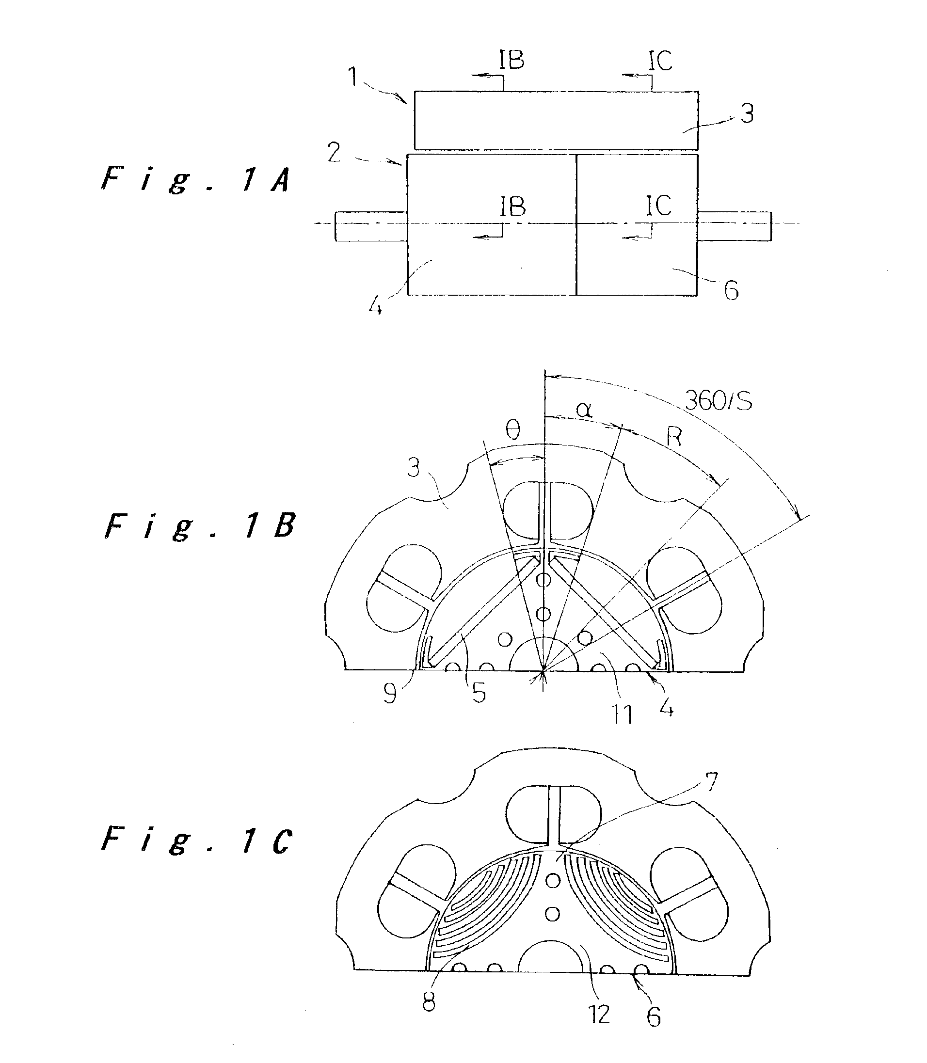
[0038]Hereinafter, a motor according to the present invention will be explained below with reference to FIGS. 1A through 2B. The entire configuration of the motor is substantially the same as that of the motor described with reference to FIG. 12, and only the main portion of the invention will be described.

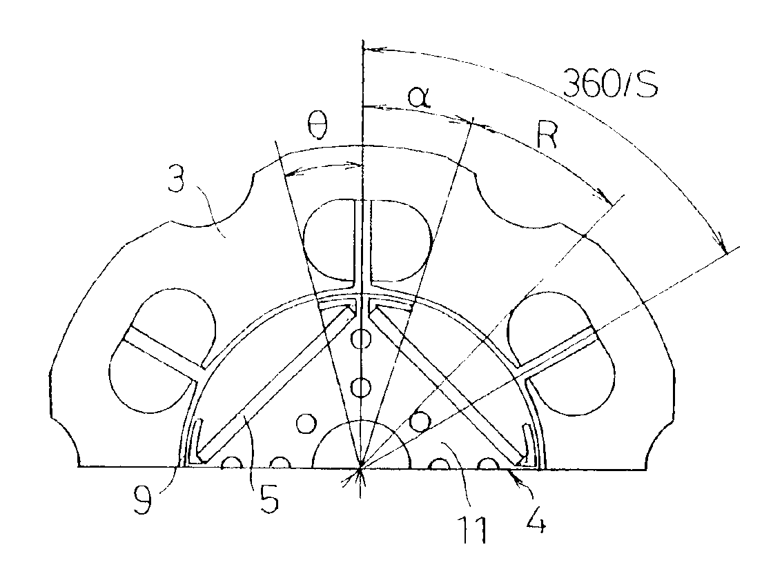
[0039]FIG. 1A shows a rotor 2 and part of a stator 3 of the motor 1. The rotor 2 of the motor 1 includes a permanent magnet type rotor unit 4 shown in FIG. 1B and a reluctance type rotor unit 6 shown in FIG. 1C. The permanent magnet type rotor unit 4 is configured to have permanent magnets 5, such as four (2n, n=2) rare-earth magnets or ferrite magnets, embedded in a rotor core 11 that has rotor-core electromagnetic steel sheets punched into a generally circular shape and stacked on top of one another. The permanent magnets 5 are arranged so as to alternate between the N and S poles along the circumferential direction.

[0040]Elongated holes 9 are arranged within a predetermined ran...

second embodiment

[0049]Now, the present invention will be described with reference to FIGS. 3 to 5H. In the following description of the embodiment, the same components as those of the previous embodiment will not be described again but only those characteristic parts will be described.

[0050]In the present embodiment, as shown in FIG. 3, the permanent magnet type rotor unit 4 and the reluctance type rotor unit 6 have a shaft hole 20 into which a rotating shaft (not shown) for connecting the rotor 2 to exterior is fitted. In order to fix the rotating shaft to the permanent magnet type rotor unit 4 and the reluctance type rotor unit 6, a plurality of keyways 21 are formed in either one or both of the shaft holes 20 in the permanent magnet type rotor unit 4 and the reluctance type rotor unit 6. The plurality of keyways 21 are formed at angle deviations δ of 0°, δ1, δ2, and δ3 (δ1 23) with respect to reference lines drawn at intervals of 180° in electric angle (in the present embodiment, at intervals of...

third embodiment

[0054]Now, the present invention will be described with reference to FIG. 6.

[0055]In this embodiment, a clearance g2 between the reluctance type rotor unit 6 and the stator 3 is made smaller than a clearance g1 between the permanent magnet type rotor unit 4 and the stator 3.

[0056]According to the present embodiment, the permanent magnet type rotor unit 4 which undergoes higher centrifugal distortion due to the provision of the permanent magnets 5 is given the greater clearance g1. Consequently, the permanent magnet type rotor unit 4 and the reluctance type rotor unit 6 are made equal in the limit of rotation speed, thereby allowing higher rotation speed. Since the clearance g1 of the permanent magnet type rotor unit 4 has a small influence on torque characteristics and the clearance g2 of the reluctance type rotor unit 6 has a great influence on the torque characteristics, the reluctance type rotor unit 6 exercises a significant effect of improving the torque characteristics. The re...


PUM


Abstract

A motor comprising: a rotor including a permanent magnet type rotor unit having a plurality of permanent magnets and a reluctance type rotor unit having a plurality of magnetic salient pole portions and a plurality of slits for preventing flux leakage, the rotor units being coupled to each other in an axial direction; and a stator for generating a field for driving the rotor. Elongated holes for preventing the short-circuit of magnetic fluxes are arranged near edges of the permanent magnet of the permanent magnet type rotor unit. The elongated holes or notches are arranged within a range defined so that 0.95α≦θ≦1.05α with α={(360/S)−R}/2 (degrees), where θ is an angle formed between a magnetic pole boundary and a center of the elongated hole or the notch in a forward direction of rotation of the rotor with respect to a center of a rotating shaft, R is an angle formed by a tooth width of the stator with respect to the center of the rotating shaft, P is the number of rotor poles, and the number of stator slots is S=3P/2.

Description

[0002]The present disclosure relates to subject matter contained in priority Japanese Patent Application Nos. 2001-259788 and 2002-189581, filed on Aug. 29, 2001 and Jun. 28, 2002 respectively, the contents of which is herein expressly incorporated by reference in its entirety.BACKGROUND OF THE INVENTION[0003]1. Field of the Invention[0004]The present invention relates to motors, and more particularly to a synchronous motor with reduced noise and vibrations in a combination of rotor structures.[0005]2. Description of the Related Art[0006]Japanese Patent Laid-Open Publication No. Hei 9-294362 discloses a Conventional synchronous motor that has different types of rotors axially coupled to each other for providing an enhanced flexibility in design. Referring to FIG. 12, a motor 1 comprises a rotor 2 having a permanent magnet rotor unit 4 and a reluctance rotor unit 6 axially coupled to each other, and a stator 3 for generating a field for driving the rotor 2. In this arrangement, the p...

Claims


Application Information

Patent Timeline
Patent Type & Authority Patents(United States)
IPC IPC(8): H02K1/27H02K16/00H02K16/02H02K19/02H02K21/14H02K19/06H02K19/10
CPCH02K1/246H02K1/2786H02K16/02B60L11/14B60L11/1803B60L11/1887B60L15/20H02K1/276B60L2270/145H02K21/14B60L2210/10B60L2210/40B60L2220/14B60L2220/18B60L2240/421B60L2240/423B60L2270/142Y02T10/70B60L50/16B60L50/51B60L58/40Y02T10/64Y02T10/72Y02T10/7072H02K1/2791Y02T90/40
Inventor TAGOME, MASAKIKONDO, YASUHIRO
Owner PANASONIC CORP
Why Eureka
Try Eureka