
Slotless motor

a slotless motor and motor body technology, applied in the direction of windings, dynamo-electric components, magnetic circuit shapes/forms/construction, etc., can solve the problems of reducing the output characteristic of the motor, increasing the manufacturing cost, and increasing the manufacturing cos

Active Publication Date: 2011-08-02
KOREA ELECTRONICS TECH INST
View PDF41 Cites 7 Cited by
  • Summary
  • Abstract
  • Description
  • Claims
  • Application Information

AI Technical Summary

Benefits of technology

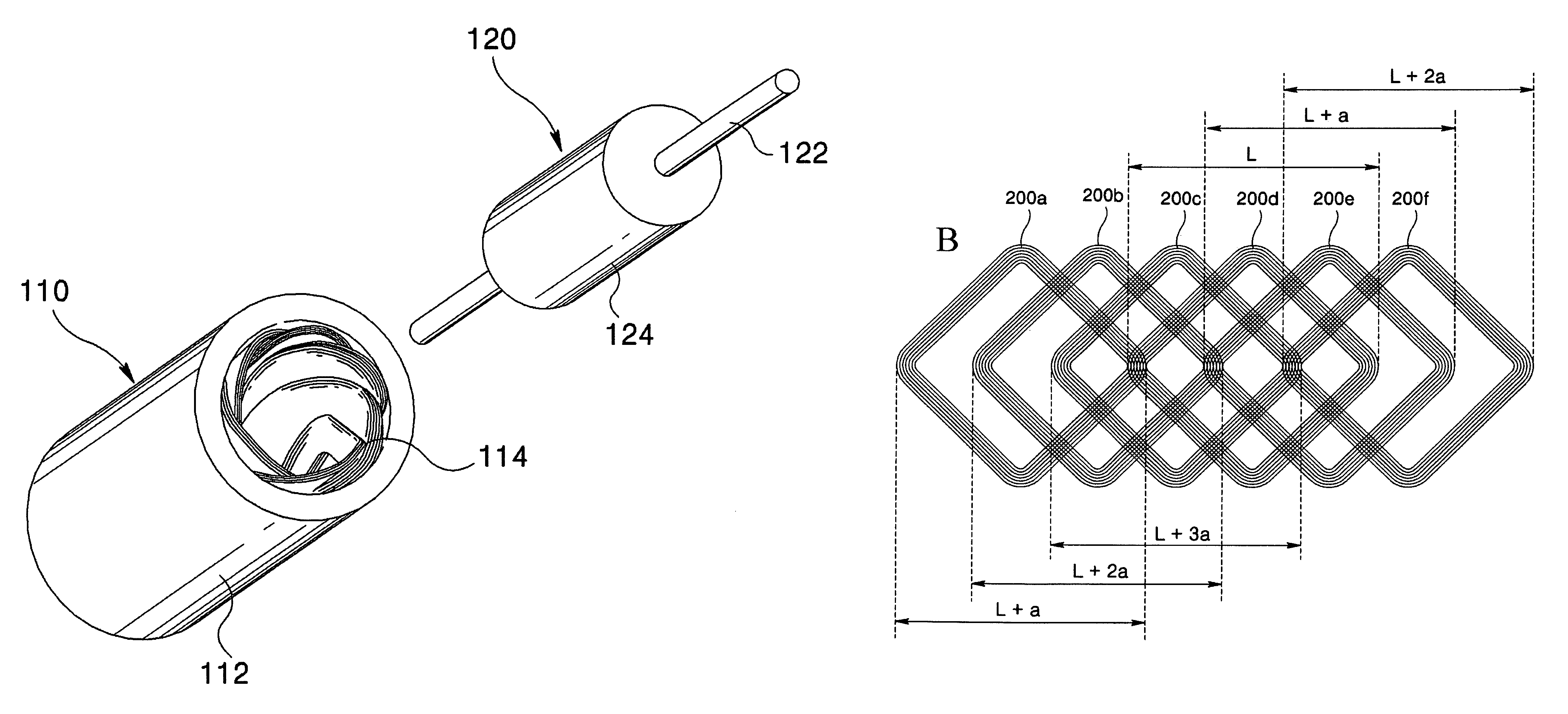
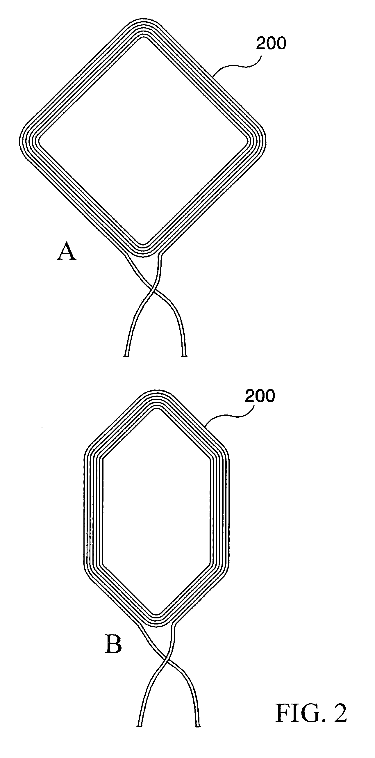
The present disclosure provides a slotless motor that can easily and accurately couple multiple unit coil bodies. The motor includes a stator with a core and stator coil, which consists of multiple unit coil bodies arranged in pairs. Each unit coil body has a different horizontal width, which allows them to be sequentially inserted into each other and form a circular coil body with a different inner diameter. The circular coil body is designed to have a different inner diameter for each phase (U, V, W) of the motor. The unit coil bodies are coupled in a plural shape to form the U, V, W phases, and the horizontal width of each unit coil body is the same. The plurality of circular coil bodies is inserted at a predetermined offset angle. The technical effect of this design is a more efficient and accurate coupling of the motor's coil bodies, resulting in improved performance and reliability.

Problems solved by technology

However, the core arranged with the slots there inside has a drawback in that it increases the manufacturing cost, and decreases the output efficiency of motor due to the difficulty in winding the insulated conductors thereon.
However, the conventional slotless motor suffers from drawbacks in that accurate offset designing and manufacturing processes are required for a precise arrangement of the plurality of unit coil bodies, and a relative distance error between the plurality of unit coil bodies is generated to decrease an output characteristic of the motor in the course of continuously arranging the plurality of unit coil bodies.

Method used


Image

  • Slotless motor
  • Slotless motor
  • Slotless motor

Examples


Embodiment Construction

[0028]The following exemplary implementations are merely exemplary and are made for the purpose of illustrating the general principles of the present disclosure. The implementations are not meant to limit the inventive concepts claimed herein. For the purpose of clarity, technical material that is known in the technical fields related to the disclosure has not been described in detail so that the disclosure is not unnecessarily obscured. Various modifications to the implementations will be readily apparent to those skilled in the art and the generic principles herein may be applied to other exemplary implementations.

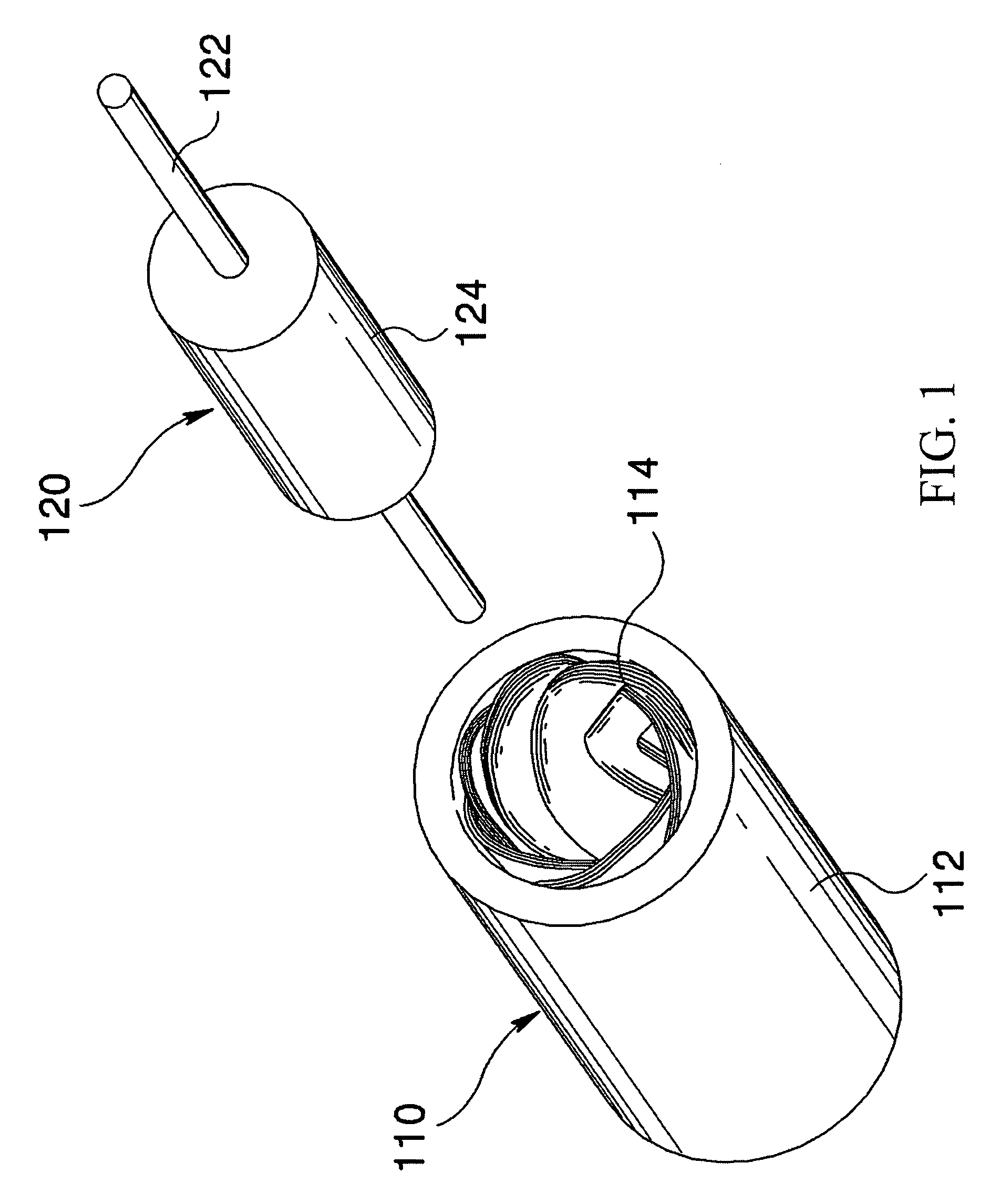
[0029]FIG. 1 is an exploded perspective view illustrating an exemplary implementation of a slotless motor according to the present disclosure, where reference numeral 110 defines a stator. The stator 110 includes a core 112, preferably a hollow cylinder, and a stator coil 114 mounted inside the core 112.

[0030]Reference numeral 120 is a rotor. The rotor may include a rota...


PUM


Abstract

A stator coil of a slotless motor is disclosed in which the stator coil is formed in such a manner that respective both distal ends of two unit coil bodies, each unit coil body arranged to face each other, are respectively coupled to form a plurality of circular coil bodies, each circular coil body having a different inner diameter, and a circular coil body having a smaller inner diameter is sequentially inserted into an inner side of a circular coil body having a larger inner diameter, whereby a horizontal width of the plurality of unit coil bodies of U, V and W phases is equal there among to cause the strength of the magnetic field of U, V and W phases to be equal, and to allow the stator to be accurately manufactured, thereby catering to a designer's intention and markedly simplifying the assembly processes.

Description

CROSS-REFERENCE TO RELATED APPLICATION[0001]The present application is based on, and claims priority from Korean Patent Application No. 10-2008-0058932, filed Jun. 23, 2008, the disclosure of which is incorporated herein by reference in its entirety.BACKGROUND[0002]1. Field of the Invention[0003]The present invention relates generally to electrical machines, and more particularly to a slotless motor.[0004]2. Description of the Background[0005]Typically, a motor is composed of a stator and a rotor. The stator is arranged at an inner side of a core formed with a plurality of slots, and stator coils are wound in the slots with insulated conductors. The rotor is arranged on a rotating axis with a permanent magnet, and is rotationally installed inside of the stator.[0006]In a case a current is applied to a stator coil of the motor, a magnetic field is generated from the stator coil, and the rotor is rotated by inter-action of the magnetic field formed by the stator coil and the magnetic ...

Claims


Application Information

Patent Timeline
Patent Type & Authority Patents(United States)
IPC IPC(8): H02K1/06
CPCH02K3/47H02K1/12H02K15/04
Inventor SEO, JUNG MOOKIM, JOO HANRHYU, SE HYUNJUNG, IN SOUNGLIM, SEUNG BINCHOI, JUN HYUKKIM, YOUNG KYOUNGU, BON GWAN
Owner KOREA ELECTRONICS TECH INST
Learn More