Visual security operations system

Inactive Publication Date: 2011-08-09
THE BOEING CO
View PDF19 Cites 64 Cited by
  • Summary
  • Abstract
  • Description
  • Claims
  • Application Information

AI Technical Summary

Benefits of technology

is to provide an improved visual security monitoring system which provides a more realistic and user-friendly display of alarm conditions.
Another object

Problems solved by technology

However, such prior art systems do not provide a

Method used


Image

  • Visual security operations system
  • Visual security operations system
  • Visual security operations system

Examples


Embodiment Construction

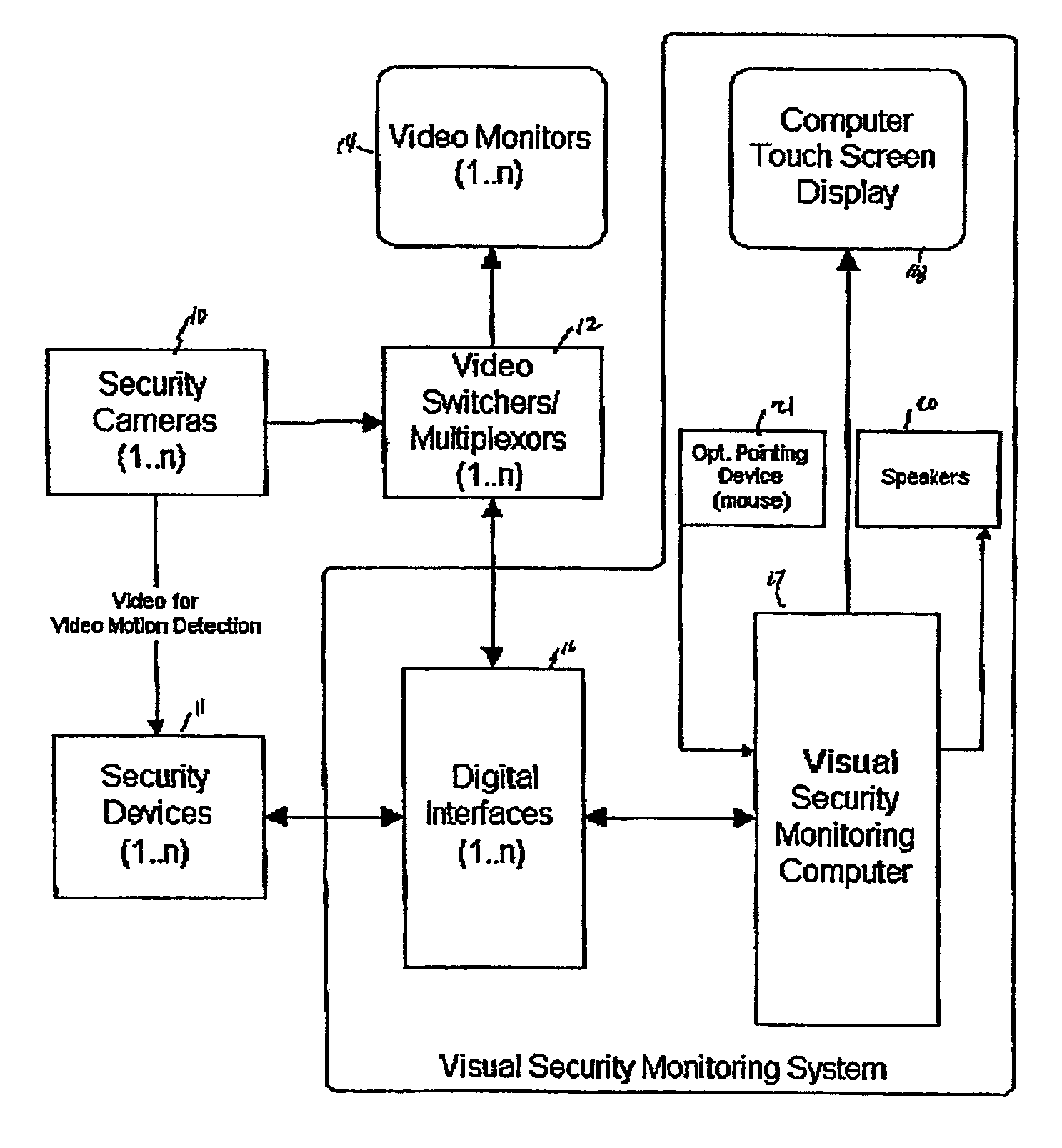
Referring initially to FIG. 10, the functional block diagram illustrates how the invention controls and communicates with other equipment at a facility. One or more video security cameras 10 are dispersed at a plurality of selected locations dispersed about the facility to be monitored and produce corresponding video signals. The security devices 11 can include a plurality of video motion detectors, one coupled to each video camera, for automatically detecting moving objects in the selected locations and producing alarm signals for each of the cameras and intrusion detectors such as infrared perimeter-intrusion detection devices (ITD), there being at least one ITD at selected locations being monitored and producing second alarm signals corresponding thereto.

The video switcher / multiplexer 12 is connected to receive video signals from the security video cameras 10 and supply them to one or more video monitors 14 and, via a digital interface 16, to the visual security monitoring comput...


PUM


Abstract

A security alarm monitor is disclosed that uses a combination of three dimensional (3D) and two dimensional (2D) visualization to display the status of security devices and allow the operator to respond to alarms. The alarm monitor console includes 3D and 2D display areas, either in a split screen on a single monitor or on dual monitors. The 3D display area uses a photo-realistic representation of a facility and overlays iconic or 3D representations of the security devices showing their locations, coverage areas, and alarm status. The 2D display area shows a map, architectural drawing, image-based overhead view, or combination or the three for a facility and security device icons. The alarm representations in the 2D and 3D display areas are synchronized. The 3D display gives a dynamic view of the facility or compound. When an alarm occurs, the 3D display flies to preprogrammed view of the alarm location, issues a preprogrammed audio alert, and animates the alarm icon to indicate its status.

Description

BACKGROUND AND BRIEF DESCRIPTION OF THE INVENTIONVideo monitoring systems for monitoring the plurality of areas in a given facility as well as incorporating sensors and alarm systems for actuating various video monitors at different sections of a facility are known. See U.S. Pat. Nos. 5,057,818, 5,144,661 and 4,141,006. However, such prior art systems do not provide a realistic presentation to the operating personnel.According to the invention, a security alarm monitor which uses a combination of three-dimensional (3D) and two-dimensional (2D) visualizations to display the status of security devices and allow the operator to respond to alarms. The alarm monitor console includes 3D and 2D display areas, either in split-screen or on a single monitor or on dual monitors. The 3D display area uses a photo-realistic representation of a facility and overlays iconic or 3D representations of a plurality of security devices, showing their locations, coverage areas, and alarm status. The 2D di...

Claims


Application Information

Patent Timeline
IPC IPC(8): H04N7/18
CPCG08B13/19691
Inventor CRESSY, CHRISTOPHERTHOMPSON, MICHAELCOX, DOUGLAS H.
Owner THE BOEING CO
Why Eureka
Try Eureka