AI technical title is built by Patsnap AI team. It summarizes the technical point description of the patent document.
a technology of an access device and an instrument, which is applied in the field of instruments access devices, can solve the problems of reducing the effective length of the surgical instrument, and achieving the effect of shortening the effective length and therefore the effective reach of the surgical instrumen
Active Publication Date: 2011-08-16
ATROPOS LTD
View PDF394 Cites 114 Cited by
Summary
Abstract
Description
Claims
Application Information
AI Technical Summary
This helps you quickly interpret patents by identifying the three key elements:
Problems solved by technology
Method used
Benefits of technology
Benefits of technology
[0008]Accessing the abdominal cavity while preserving the abdominal wall as much as possible is the aim of any surgical or exploratory procedure. Retraction devices have been used to this end. A retractor can help to expose an operative site and minimise the incision required to carry out the operation.
[0010]The use of a cannula to gain access as a means to see inside the abdomen or introduce surgical instruments has existed since the late 19th century. A cannula comprises a rigid tube, which is inserted through the abdominal wall and is held in place by the tension of the abdominal wall itself around the inserted cannula. The tube must accommodate various thicknesses of abdominal wall and extend significantly both inside and outside the abdomen to avoid slipping out of the incision, and thereby causing gas pressure to escape.
[0012]1. A cannula is held in place, and thus prevents the escape of gas, by tissue tension. This tension can vary depending on the way the cannula is introduced or weaken during the operation under normal surgical manipulation.
[0016]5. A cannula takes up a significant space outside of the abdomen, shortening the effective length, and therefore reach, of the surgical instrument.
Problems solved by technology
The basic construction of a cannula, however, presents significant limitations in carrying out a surgical procedure.
This tension can vary depending on the way the cannula is introduced or weaken during the operation under normal surgical manipulation.2. A cannula extends significantly into the abdominal cavity taking up precious space and interfering with other instruments.3. A cannula restricts the movement of instruments as they are rigid structures.4. A rigid cannula presents significant limitations on the design of the instrument which must be passed through the cannula.5. A cannula takes up a significant space outside of the abdomen, shortening the effective length, and therefore reach, of the surgical instrument.
Method used
Image
Click on the blue label to locate the original text in one second.
Reading with bidirectional positioning of images and text.
Examples
Embodiment Construction
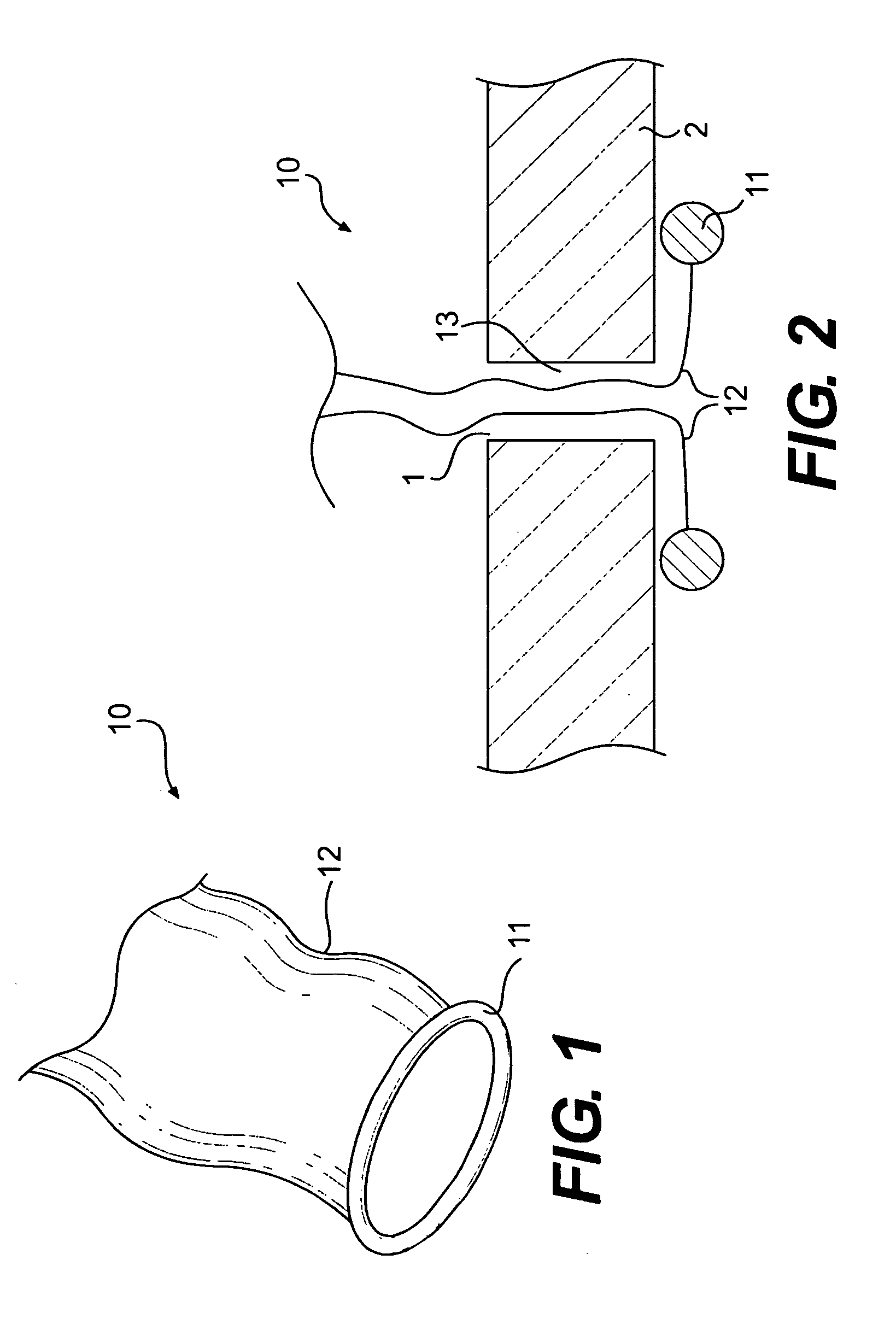
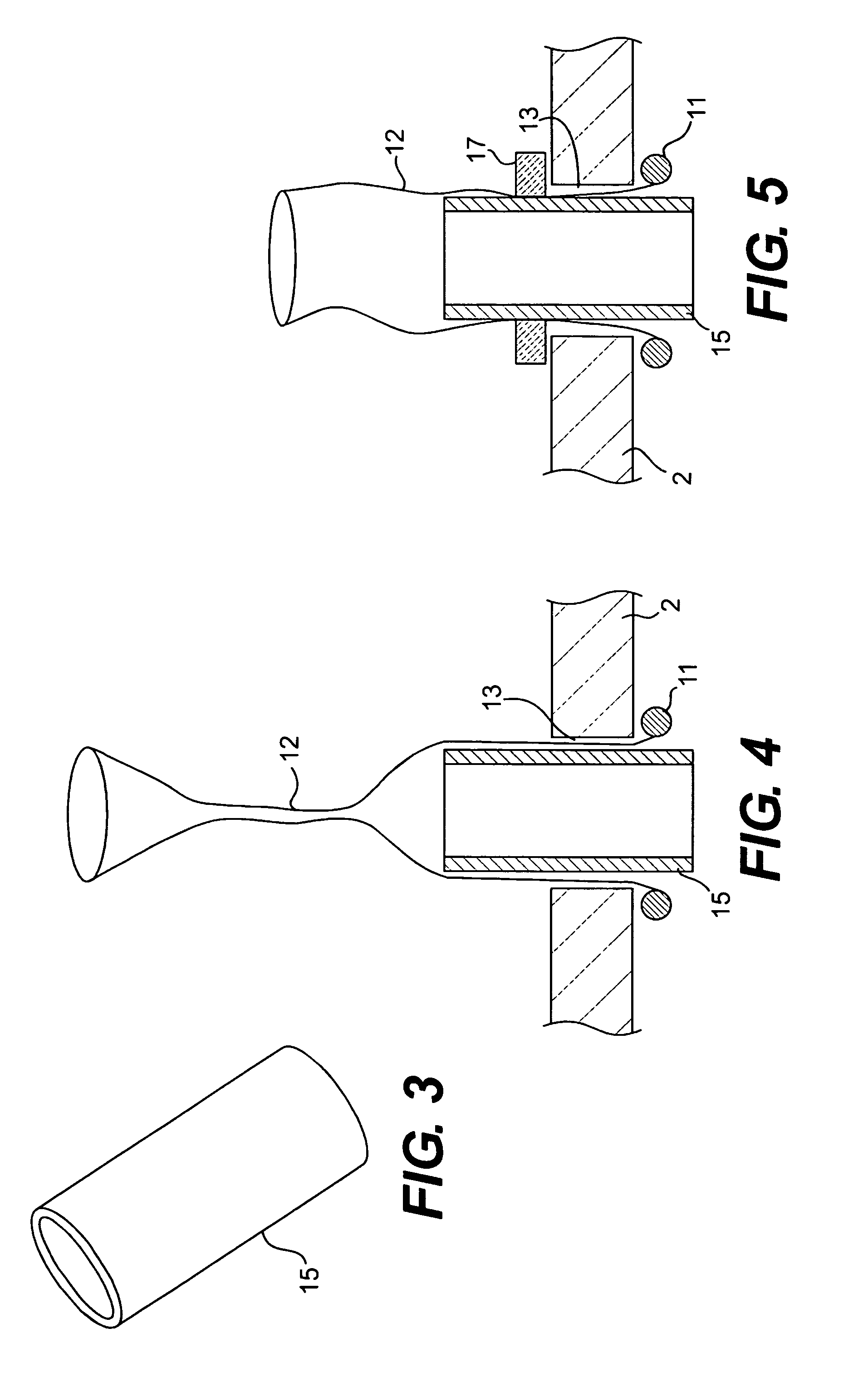
[0151]Referring to the drawings there are illustrated various instrument access devices of the invention for an incision 1, for example in an abdominal wall 2. The construction of the various components and their attributes will be explained in detail below. In some cases, the instrument access device is used as a substitute for a conventional rigid tubular cannula. The instrument access devices of the invention may be used to provide access to the abdominal cavity by an instrument 3, which in this case has an operating element 4, such as a surgical stapler, mounted at the distal end of a flexible shaft 5.
[0152]It will be noted that the devices have a very low profile, especially with respect to the inside of the incision 1. The devices are positively retained in the incision 1 against pull-out forces. Because of the low profile the shaft 5 of the instrument 3 can begin bending immediately after entering the abdominal cavity. The amount of free space required to manipulate the instr...
PUM
Abstract
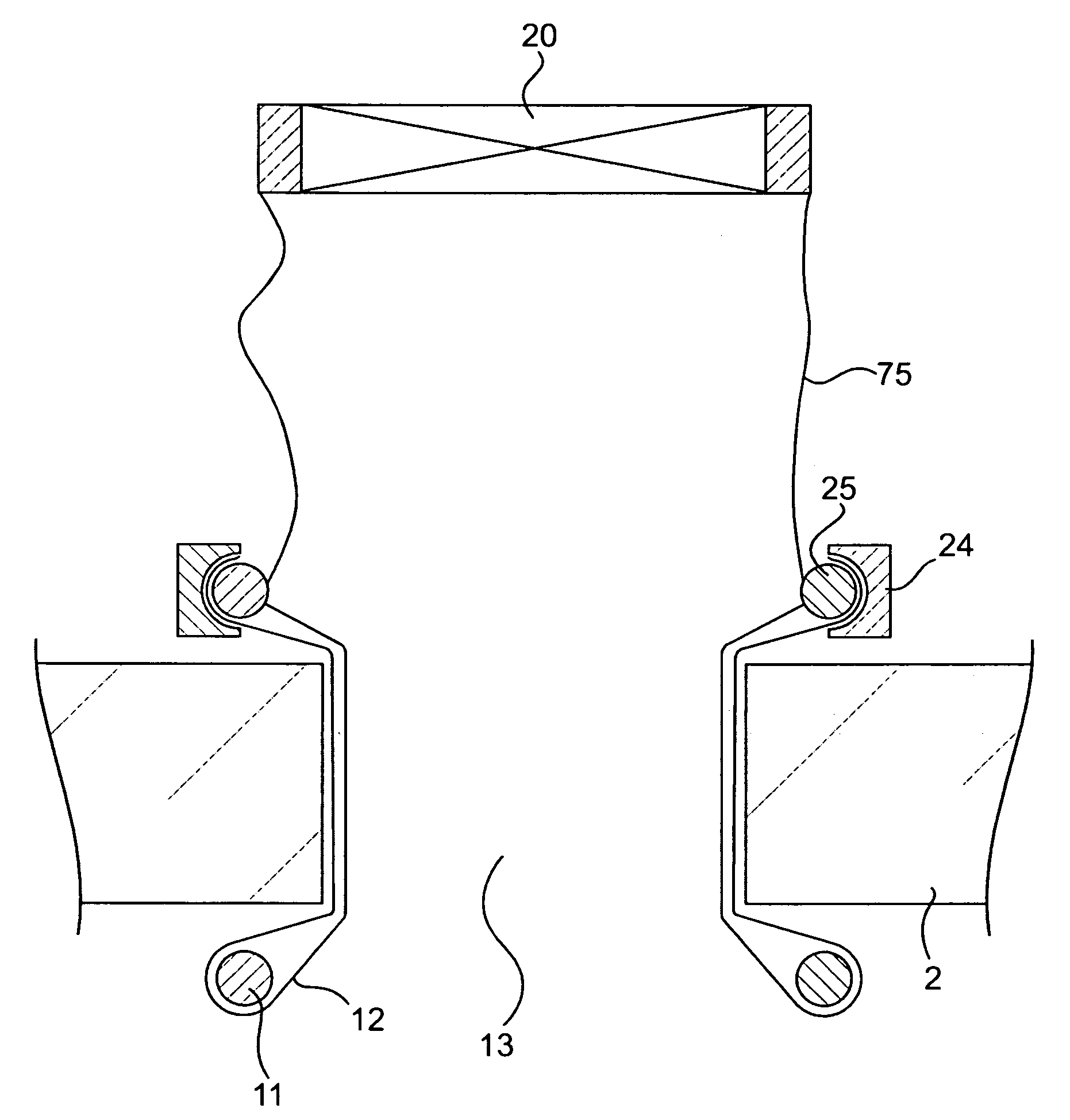
An instrument access device (500) comprises a distal O-ring (11) for insertion into a wound interior, a proximal member for location externally of a wound opening and a sleeve (12) extending in two layers between the distal O-ring (11) and the proximal member. The proximal member comprises an inner proximal ring member (25) and an outer proximal ring member (24) between which the sleeve (12) is led. A seal housing (300) is mounted to the inner proximal ring member (25). A gelatinous elastomeric seal (302) with a pinhole opening (303) therethrough is received in the housing (300). An instrument may be extended through the seal (302) to access the wound interior through the retracted wound opening in a sealed manner.
Description
[0001]This application is a Continuation-In-Part of U.S. application Ser. No. 10 / 736,234, filed Dec. 16, 2003, which claims the benefit of U.S. Provisional Application Nos. 60 / 433,603, filed on Dec. 16, 2002, and 60 / 453,200, filed on Mar. 11, 2003.[0002]This application is also a Continuation-In-Part of U.S. application Ser. No. 10 / 678,653, filed Oct. 6, 2003, which is a Continuation-In-Part of 10 / 133,979, filed on Apr. 29, 2002, which is a Continuation of U.S. application Ser. No. 09 / 801,826, filed on Mar. 9, 2001, which is a Continuation of PCT / IE99 / 00122, filed Dec. 1, 1999, and also a Continuation-In-Part of U.S. application Ser. No. 10 / 374,523, filed on Feb. 27, 2003, which is a Continuation of U.S. application Ser. No. 09 / 849,341, filed on May 7, 2001, which is a Continuation of U.S. application Ser. No. 09 / 688,138, filed Oct. 16, 2000, and claims the benefit of U.S. Provisional Application Nos. 60 / 415,780, filed on Oct. 4, 2002; 60 / 428,215, filed on Nov. 22, 2002 and 60 / 490,9...
Claims
Application Information
Patent Timeline
Application Date:The date an application was filed.
Publication Date:The date a patent or application was officially published.
First Publication Date:The earliest publication date of a patent with the same application number.
Issue Date:Publication date of the patent grant document.
PCT Entry Date:The Entry date of PCT National Phase.
Estimated Expiry Date:The statutory expiry date of a patent right according to the Patent Law, and it is the longest term of protection that the patent right can achieve without the termination of the patent right due to other reasons(Term extension factor has been taken into account ).
Invalid Date:Actual expiry date is based on effective date or publication date of legal transaction data of invalid patent.

