
Incentive spirometry devices by the employment of verbal simulated humanlike voices and using a capacitive sensing component for determining patient use and measurement obtained from such use
a technology of spirometry and spirometer, which is applied in the direction of volume/mass flow by dynamic fluid flow effect, medical science, diagnostics, etc., can solve the problems of patient unsupervised therapy, difficulty in reading the scale, and improperly performed therapy, so as to improve the performance of inspiratory muscles, prevent or reverse lung atelectasis, and increase the transpulmonary pressure and respiratory volume
- Summary
- Abstract
- Description
- Claims
- Application Information
AI Technical Summary
Benefits of technology
Problems solved by technology
Method used
Image

Examples
Embodiment Construction
;
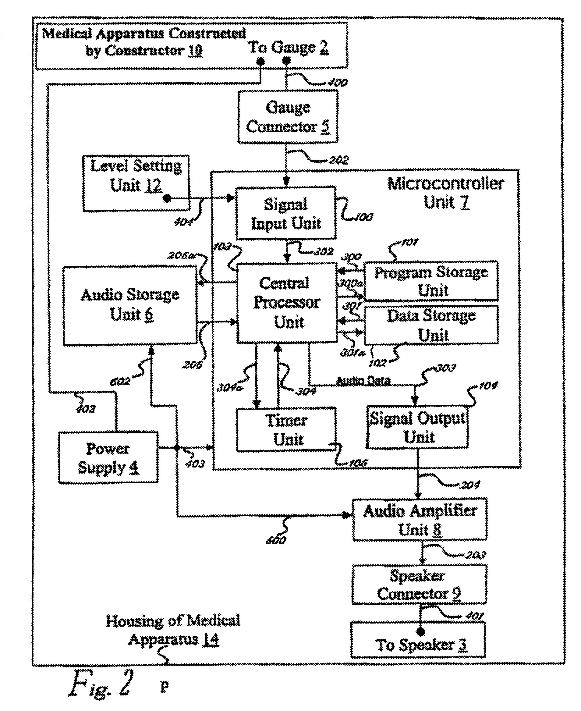
[0031]FIG. 2 shows the Preferred Embodiment of the Audible Response Unit;
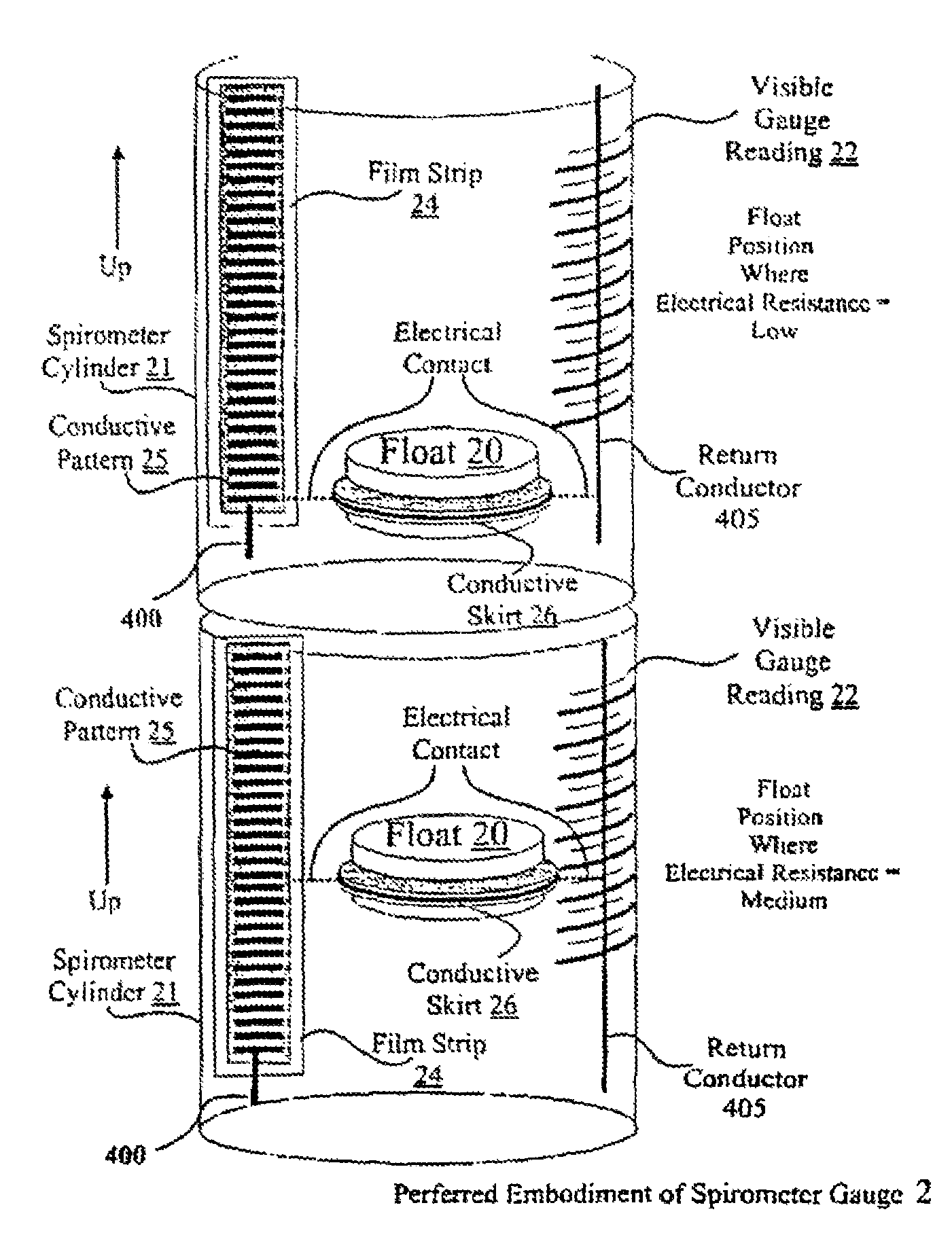
[0032]FIG. 3 shows the details of the Gauge;
[0033]FIG. 4 shows the Present invention within the housing of a Medical Apparatus;
[0034]FIG. 5 shows the details of the Deactivation Key 17;
[0035]FIG. 6 illustrates several views of one Incentive Spirometer embodiment for the present invention showing the Incentive Spirometer having a float stop member;
[0036]FIG. 7 illustrates a screen shot for the PC software interface for communicating with the Incentive Spirometer of the present invention;
[0037]FIG. 8 illustrates a schematic view of the resistive method for sensing movement of the float; and
[0038]FIG. 9 illustrates a general configuration of the capacitive method for sensing movement of the float as an alternative sensing method.
DETAILED DESCRIPTION OF THE INVENTION
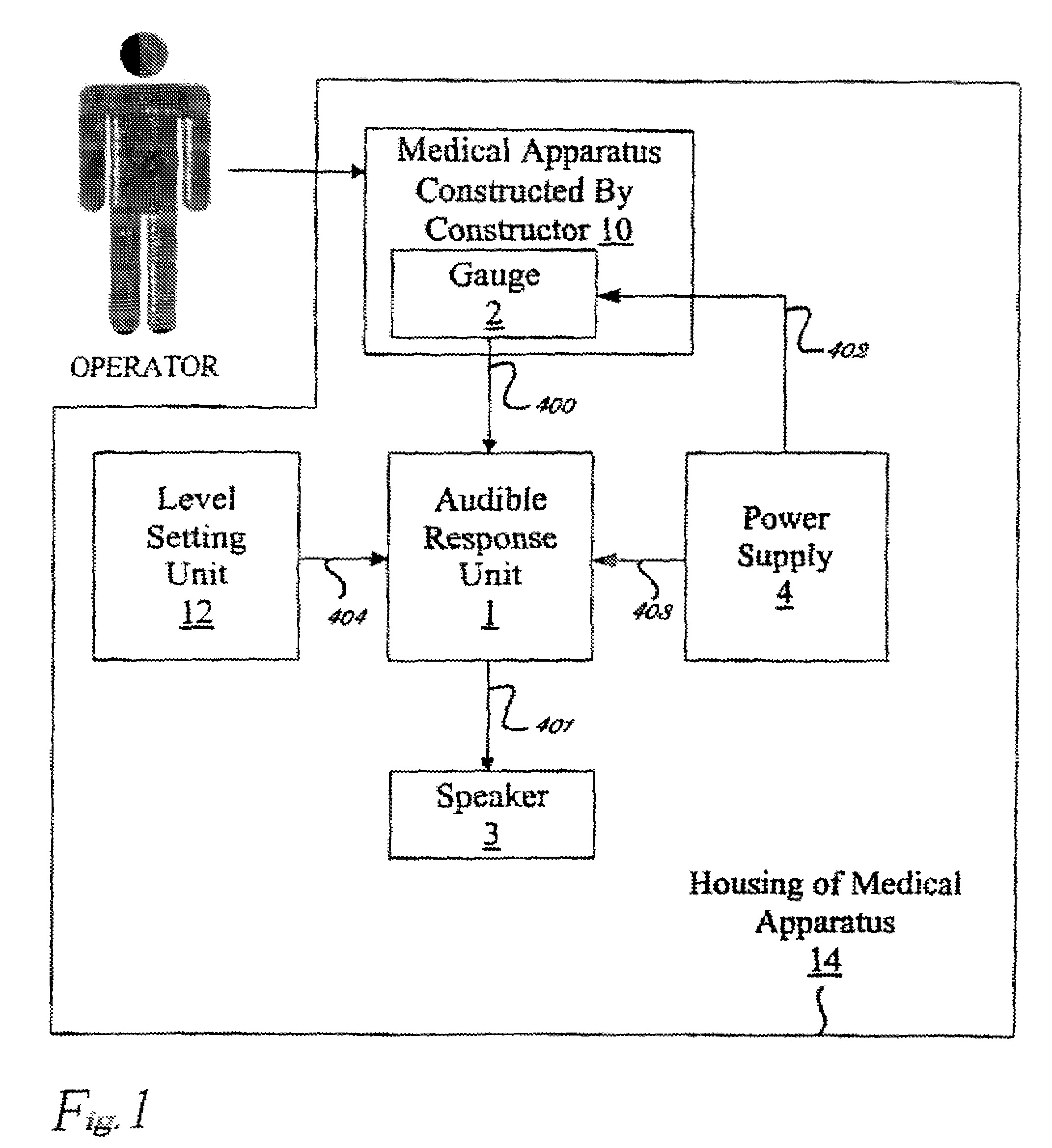
[0039]Now referring to the drawings the present invention will be further described. FIG. 1 shows a preferred embodiment of present invention. A Gauge...
PUM
 Abstract
Description
Claims
Application Information