
Support for chest compression system

a chest compression and support device technology, applied in the field of chest compression systems, can solve the problems of virtually impossible to give manual cpr of sufficient quality during the transportation of patients, and the collar does not permit adaptation to different patient sizes and shapes

Inactive Publication Date: 2011-08-23
LAERDAL MEDICAL AS
View PDF38 Cites 30 Cited by
  • Summary
  • Abstract
  • Description
  • Claims
  • Application Information

AI Technical Summary

Benefits of technology

"The invention is a support for a chest compression device that can adjust its size to accommodate different patients. It has a back plate and front part with a seat for chest compression, and side parts that connect the back plate to the front part. The support has a patient-receiving surface that can be adjusted in size to limit the movement of patients. The side parts can be telescopic lockable legs or hinges to provide adjustable length. The technical effect of this invention is to provide a flexible and adjustable support for chest compression that can accommodate different patients and ensure effective compression."

Problems solved by technology

Performing chest compressions manually is an extremely exhausting task, and it is practically impossible to give manual CPR of sufficient quality during transportation of a patient.
The collar does not permit adaptation to different patient sizes and shapes.
The compression belt compresses and decompresses the chest of a patient, but it can easily get caught in the patient's clothes.
For this reason the patient must be unclothed before the chest compression procedure can start, and valuable time is lost.
The belt also covers a large area of the patient's chest and can thus interfere with defibrillation electrodes.
This vacuum cup will get correctly fixed in some patients but will displace on the chest in other patients leading to incorrect or unstable chest compressions.
The above-mentioned devices are either complicated and time-consuming to apply, cumbersome to install and operate, or are unstable on the chest.
They are further heavy and expensive to purchase.

Method used


Image

  • Support for chest compression system
  • Support for chest compression system
  • Support for chest compression system

Examples


first embodiment

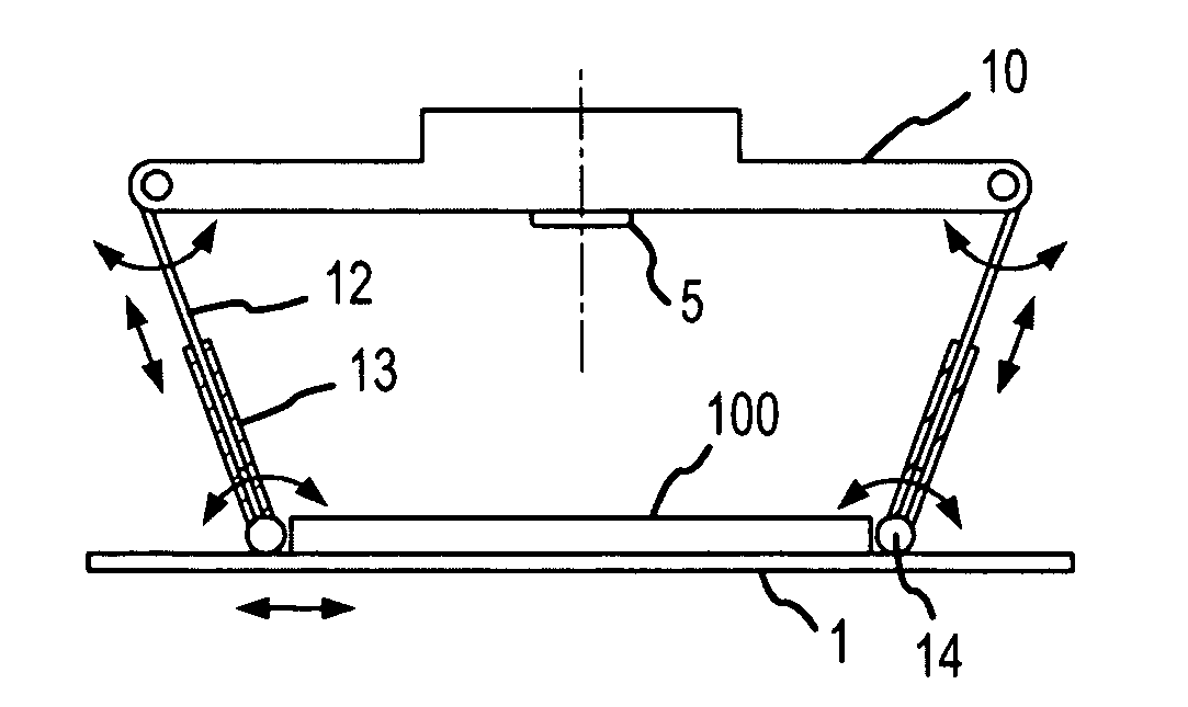
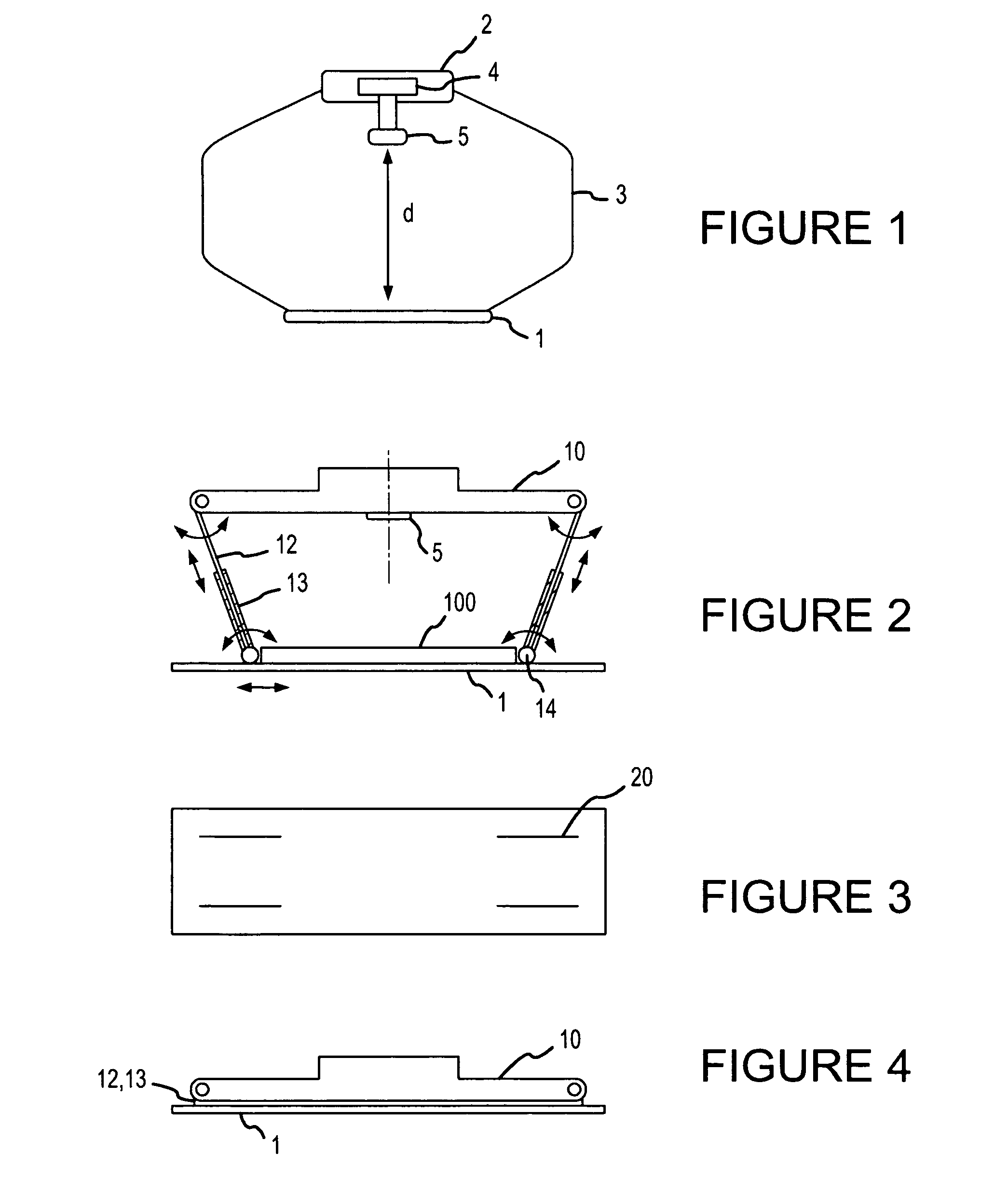
[0018]FIG. 2 shows the invention. In this embodiment of the invention the front part comprises a transverse plate 10 where the chest compression system is situated. The chest compression system comprises in this embodiment of the invention a chest compression member 5 in the form of a piston, a transmission mechanism for transmitting energy to the piston, a motor, and a power supply (not shown). Part of the chest compression system may be situated externally to the support, and the support may be mechanically attached to the compression member 5.

[0019]In this embodiment of the invention, the transverse plate 10 is substantially rectangular and is coupled on its short edges to two lateral legs. Each of the legs is formed an upper part 12 and a lower part 13. The upper part 12 is hinged to the transverse plate 10 and is also situated telescopically inside the lower part 13. This arrangement permits easy adaptation of the legs' length to the patient's chest height. The devices for lock...

second embodiment

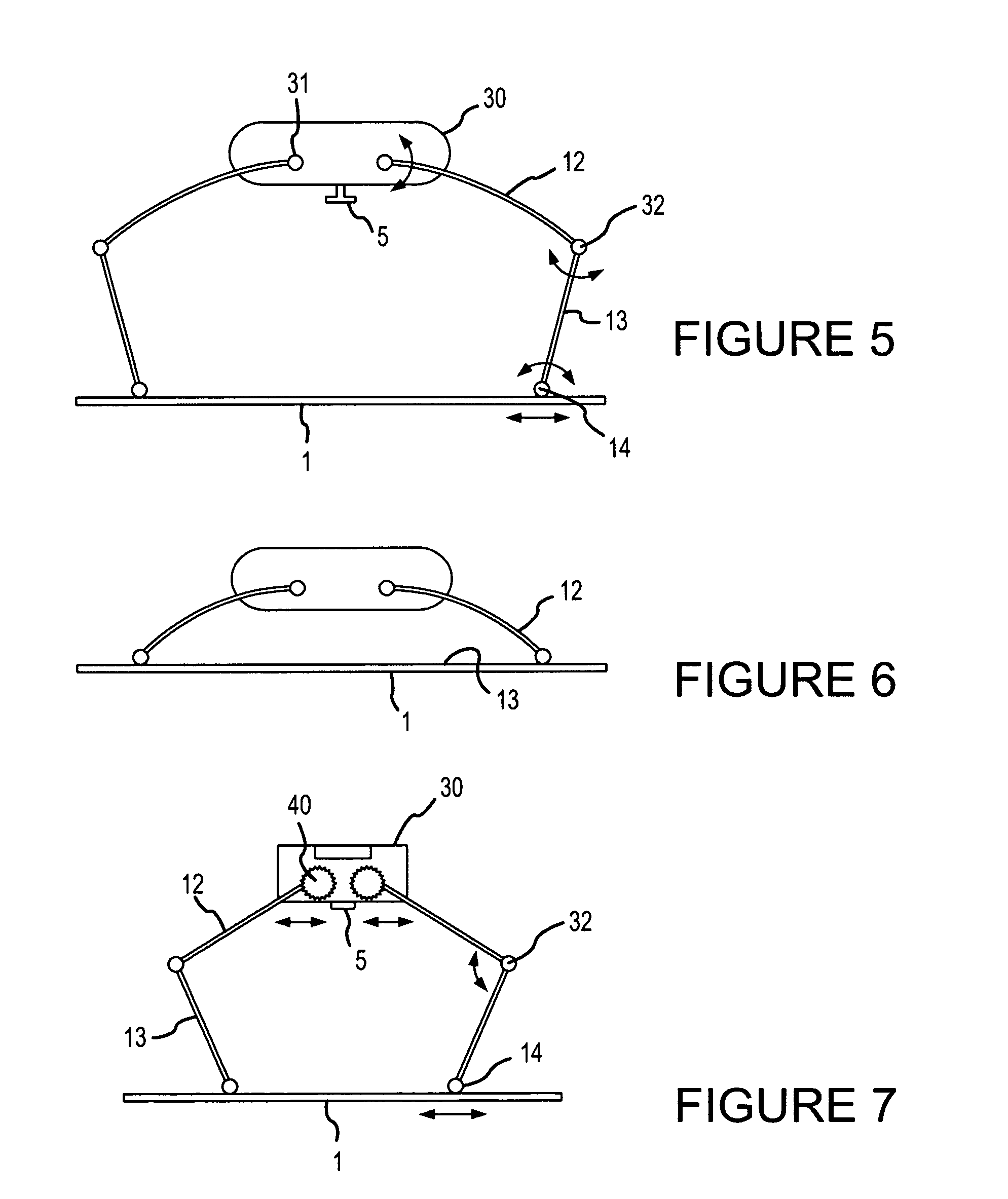
[0028]FIG. 5 shows the invention. In this embodiment, the chest compression system is situated in a body 30. The upper parts of the legs 12 are rotatably connected to the body 30 by means of hinges 31 or similar devices. Hinges 31 are situated in the vicinity of one another and, in one embodiment of the invention, are interconnected. The upper and lower parts of each leg (12 and 13 respectively) are also rotatably coupled to one another by means of hinges 32. In one embodiment of the invention, the hinges 31 and 32 also provide locking of the body 30 at a determined distance from the back plate 1. The lower part of each leg is rotatably and slidably connected to back plate 1. The chest compression system can be divided into a first and a second element in a manner similar to that described above in relation to FIGS. 1-4.

[0029]As mentioned earlier the support according to the various embodiments of the invention can be provided with devices to ensure symmetry with respect to the pati...

third embodiment

[0030]FIG. 7 shows the invention where block 30 includes elements 40 that can rotate and slide. A connection between the lower part of legs 13 and plate 1 permits sliding but rot rotation.


PUM


Abstract

A support for a chest compression system includes a back plate, a front part having a seat for a compression member of a chest compression system, and a side part connecting the back plate to the front part. The side part is adapted to provide adjustable spacing between the seat and the back plate to accommodate patients having different chest heights to allow the support to be snugly placed around the chest of a patient.

Description

TECHNICAL FIELD[0001]This invention is related to resuscitation systems, and more particularly to a support device for a chest compression system and a chest compression system provided with such a support.BACKGROUND OF THE INVENTION[0002]Sudden cardiac arrest is a leading cause of death in developed countries in the Western World, like the United States and Canada. To increase the chance for survival from cardiac arrest, important aspects are CPR (Cardio Pulmonary Resuscitation) and heart defibrillation given in the first few critical minutes after the incident. CPR is performed to ensure a sufficient flow of oxygenated blood to vital organs by external compression of the chest combined with rescue breathing. Heart defibrillation is performed to re-establish normal heart rhythm by delivery of an external electric shock. The quality of CPR is essential for survival. Chest compressions must be given with a minimum of interruptions, and be of sufficient depth and rate. Performing ches...

Claims


Application Information

Patent Timeline
Patent Type & Authority Patents(United States)
IPC IPC(8): A61H31/00A61H23/00
CPCA61H31/00A61H31/006A61H31/008
Inventor HANSEN, FREDERIKTJOLSEN, OYVIND
Owner LAERDAL MEDICAL AS
Learn More