Device and method for connecting interrupted recording

a technology of interrupted recording and device, applied in the field of optical recording devices, can solve the problems of recording failure, incorrect reconnection of data, errors in reconnecting and reading data,

Inactive Publication Date: 2011-08-23
MEDIATEK INC
View PDF6 Cites 0 Cited by
  • Summary
  • Abstract
  • Description
  • Claims
  • Application Information

AI Technical Summary

Benefits of technology

[0008]Accordingly, an objective of the present invention is to provide a method and an optical recording apparatus to generate a data-interrupted address when data recording is interrupted and to reconnect the interrupted data from a data-reconnecting physical address, so as to continue to reconnect the interrupted data from the data-reconnecting physical address, which enables further correct reading.
[0010]According to the present invention, the optical recording device records a plurality of data onto the optical storage medium. When data recording is interrupted, the data-interrupt address generator can generate the data-interrupt address, and the data-reconnecting physical address generator can generate the data-reconnecting physical address according to the data-interrupt address, to enable reconnect the interrupted data from the data-reconnecting physical address. Therefore, the present invention prevents incorrect reconnection when data recording is interrupted.

Problems solved by technology

During recording, some shock error or abnormal condition may occur to interrupt recording and the interrupted data cannot be correctly reconnected.
As a result, recording is failed.
In the system with high recording / reading speed, particularly, errors may occur when reconnecting and reading data after data recording is interrupted.
Therefore, it is an important issue to reduce errors in data reconnection and consequently reduce read errors.

Method used


Image

  • Device and method for connecting interrupted recording
  • Device and method for connecting interrupted recording
  • Device and method for connecting interrupted recording

Examples


Embodiment Construction

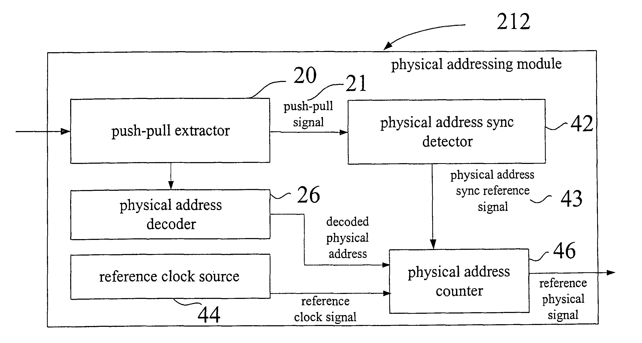
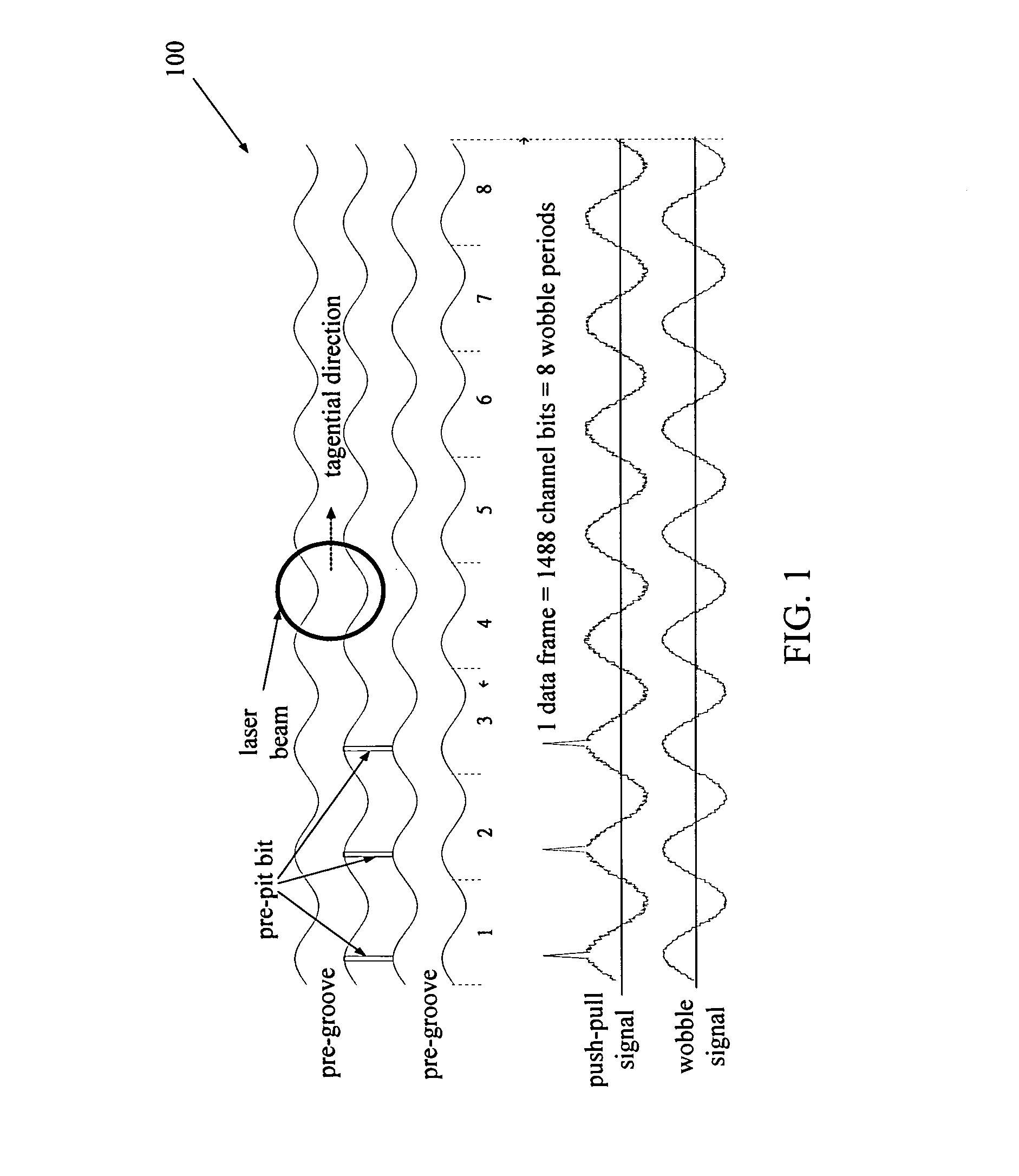
[0028]For various types of optical storage medium, e.g. disks of CD-R / RW, DVD+R / RW and DVD-R / RW, digital data are recorded in a spiral-shaped pre-groove on the optical storage medium. The pre-groove is wobbly and the wobble frequency can be used to control the recording speed. The pre-groove on the optical storage medium comprises address information corresponding to a location on the optical storage medium. Such address information is called physical address and used for ensuring data to be recorded in correct positions on the optical storage medium.

[0029]For a DVD disc, for example, the recorded data has four types of data structure unit, including channel bit, data frame, data sector, and ECC block (error correction code block). Channel bit is the smallest recording unit on the disc. One byte data can be modulated into 16 channel bits with EFM+ (Eight to Fourteen Modulation Plus) modulation and then be recorded on the disc. EFM+ allows the continuous extend of the same signal sta...


PUM

PropertyMeasurementUnit
wobble frequencyaaaaaaaaaa
thresholdaaaaaaaaaa
frequencyaaaaaaaaaa

Abstract

This invention provides an optical storage device for recording a plurality of data onto an optical storage medium. If recording interrupted, the optical storage device generates a data-interrupted address, and re-connects the interrupted data with a data re-connecting physical address. The optical storage device comprises a physical addressing module, a record-interrupt generator, a data recording controller, a data-interrupt address generator and a data-reconnecting physical address generator. The physical addressing module provides a reference physical address for recording data onto the optical storage medium. When detecting the interrupt of data recording, the data-interrupt address generator generates the address of the interrupted data. According to the address of the interrupted data, the data-reconnecting physical address generator generates a data-reconnecting physical address. The optical storage device utilizes the data-reconnecting physical address to continue to record the interrupted data onto the optical storage medium.

Description

[0001]This is a division of application Ser. No. 10 / 639,808 filed Aug. 13, 2003 now U.S. Pat. No. 7,379,401.BACKGROUND OF THE INVENTION[0002]1. Field of the Invention[0003]The present invention relates to an optical recording device for recording a plurality of data onto an optical storage medium. In particular, the optical recording device can generate a data-interrupt address when recording is interrupted, and then continue to reconnect the interrupted data from a data-reconnecting physical address.[0004]2. Description of the Prior Art[0005]The optical recording system is developing with the trend towards high recording / reading speed, and high memory capacity.[0006]Optical recording devices, such as conventional CD-R / RW and DVD-R / RW recorders, are used to record data onto corresponding optical storage medium, such as various types of CD, VCD and DVD recordable disks). During recording, some shock error or abnormal condition may occur to interrupt recording and the interrupted data...

Claims


Application Information

Patent Timeline
Patent Type & Authority Patents(United States)
IPC IPC(8): G11B7/00G11B7/0045G11B20/12G11B20/14G11B27/24
CPCG11B20/10425G11B20/1217G11B20/1403G11B7/0045G11B27/24G11B2220/2537G11B2020/1268G11B2020/1287G11B2220/216G11B2220/218G11B2020/10972
Inventor WU, WEN-YICHEN, HONG-CHING
Owner MEDIATEK INC
Why Eureka
Try Eureka