Outer operational device for panic exit door lock

a technology for exiting doors and operating devices, which is applied in the direction of building locks, door/window fittings, construction, etc., can solve the problems of requiring troublesome installation and providing the burglarproof function by itsel

Active Publication Date: 2011-09-06
I TEK METAL MFG
View PDF12 Cites 20 Cited by
  • Summary
  • Abstract
  • Description
  • Claims
  • Application Information

AI Technical Summary

Problems solved by technology

However, troublesome installation is required when mounting such a door latch assembly to a differently handed door.
Furthermore, such a door latch assembly can not provide the burglarproof function by itself, so that it must be utilized with a door lock with a burglarproof function.

Method used


Image

  • Outer operational device for panic exit door lock
  • Outer operational device for panic exit door lock
  • Outer operational device for panic exit door lock

Examples


Embodiment Construction

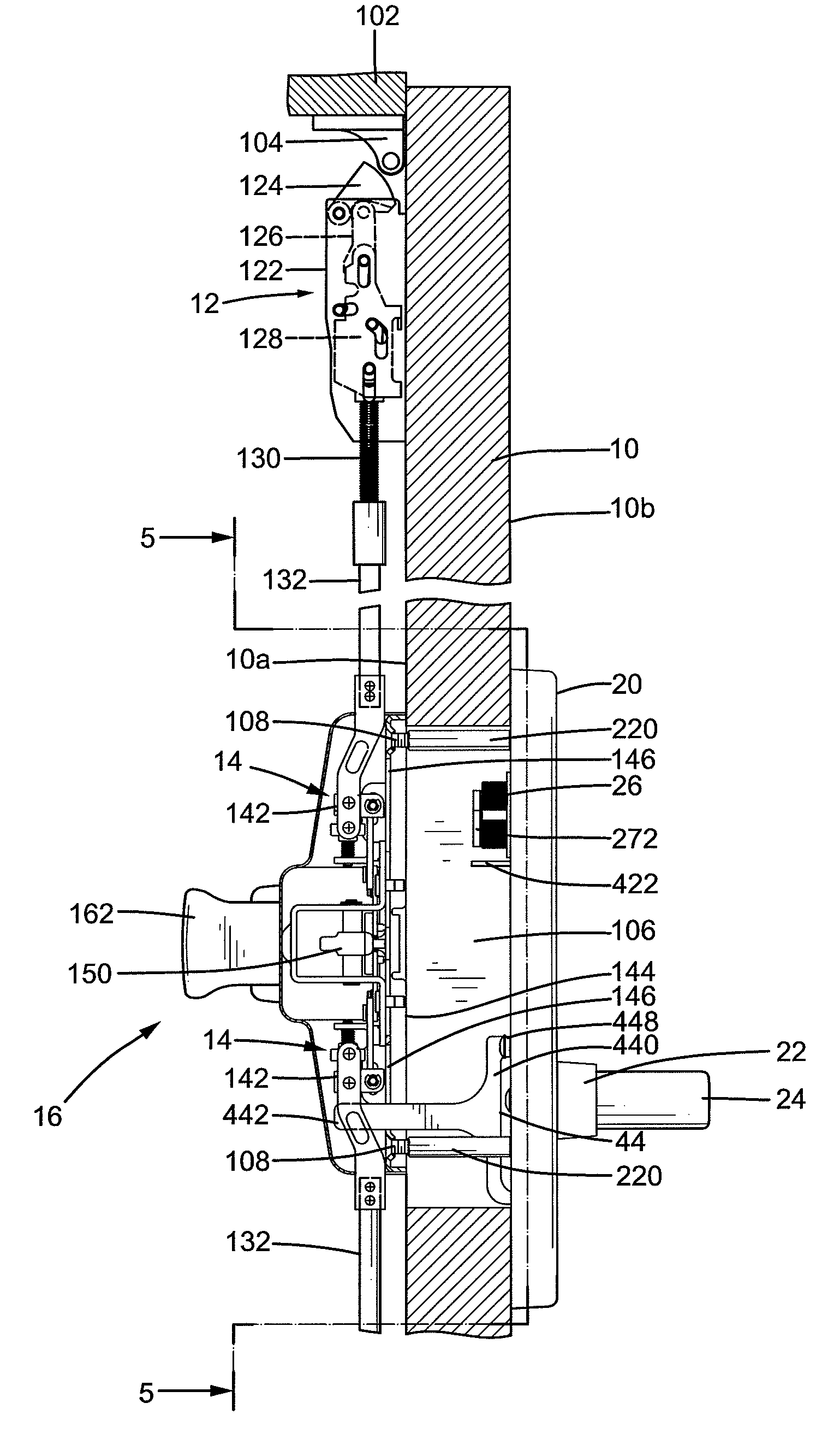
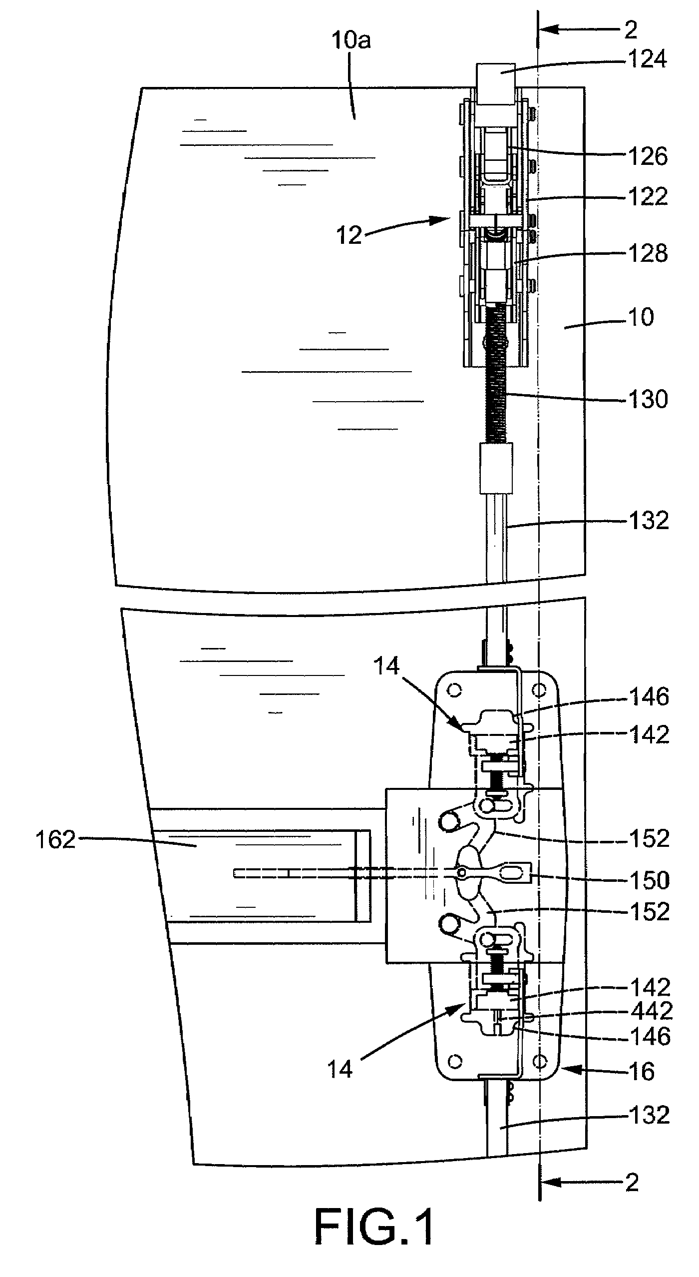
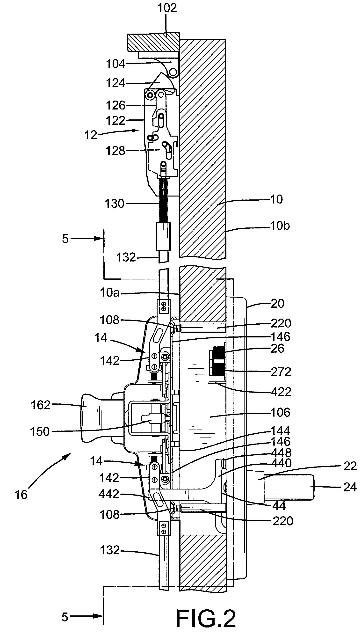
[0026]An outer operational device according to the preferred teachings of the present invention is shown in the drawings and adapted to be mounted to a side of a door 10 for operating a lock mounted to the other side of door 10. According to the preferred form shown, the lock includes a follower device 16 and a latch device 12 operably connected to follower device 16. Door 10 is hinged to a door frame 102 and includes an inner side 10a and an outer side 10b. It is noted that inner and outer sides 10a and 10b are exchanged when door 10 is installed as a differently handed door. According to the most preferred form shown, door 10 is installed as a right-handed door. Furthermore, door 10 includes a mounting hole 106 extending from inner side 10a through outer side 10b. Door frame 102 includes top and bottom strikers 104. When door 10 is closed, inner side 10a abuts against an end face of door frame 102. Follower device 16 and latch device 12 are mounted to inner side 10a of door 10, an...


PUM


Abstract

An outer operational device includes a cover mounted to a side of a door. An actuating member is mounted in the cover and includes an end engaged with a handle to rotate therewith. A sliding member is slideably received in the cover and operably connected to the actuating member, so that the sliding member slides when the actuating member rotates. A limiting member is pivotably received in the cover between a blocking position not allowing movement of the sliding member and a release position allowing movement of the sliding member. The handle is rotatable when the limiting member is in the release position. The handle is not rotatable when the limiting member is in the blocking position. A key-operable lock core is operably connected to the actuating member, so that the limiting member can be moved to the blocking position to provide a burglarproof function.

Description

BACKGROUND OF THE INVENTION[0001]The present invention relates to an outer operational device for a panic exit door lock and, more particularly, to an outer operational device for a panic exit door lock that includes a handle for unlocking purposes.[0002]Panic exit door locks of the type having top and bottom latches for burglarproof purposes generally include an outer operational device that can be operated to unlock the door. U.S. Pat. No. 5,570,916 discloses a door lever assembly for disengaging an unlocked latch of a lockable door latch assembly. The door lever assembly includes a lever handle rotatably connected to a trim housing supporting a stop plate. A cam is operably connected to the lever handle and positioned to rotate in response to rotation of the lever handle, converting its rotational movement to linear movement of a movable slider positioned adjacent to the cam. A lift arm is operably connected to vertical rods of the door latch assembly, and an over-ride spring is ...

Claims


Application Information

Patent Timeline
Patent Type & Authority Patents(United States)
IPC IPC(8): E05B3/00
CPCE05B65/1006Y10T70/5159Y10T292/0822Y10T292/0908Y10T292/57
Inventor TIEN, HUNG-JENHUANG, CHEN-WEI
Owner I TEK METAL MFG
Why Eureka
Try Eureka