Al technical title is built by PatSnap Al team. It summarizes the technical point description of the patent document.
a surgical system and surgical technology, applied in the field of electromechanical surgical system surgical attachment, can solve the problems of surgical instruments being damaged, orifice of the body being damaged, patient being harmed,
Active Publication Date: 2011-09-27
COVIDIEN LP
View PDF634 Cites 2090 Cited by
Summary
Abstract
Description
Claims
Application Information
AI Technical Summary
This helps you quickly interpret patents by identifying the three key elements:
Problems solved by technology
Method used
Benefits of technology
[0212]Thus, the several aforementioned objects and advantages of the present invention are most effectively attained. Those skilled in the art will appreciate that numerous modifications of the exemplary embodiment described hereinabove may be made without departing from the spirit and scope of the invention. Although a single exemplary embodiment of the present invention has been described and disclosed in detail herein, it should be understood that this invention is in no sense limited thereby and that its scope is to be determined by that of the appended claims.
Problems solved by technology
One of the problems experienced during surgical procedures of this type is that the orifice of the body may be damaged when the surgical instrument is being introduced, or has been introduced, into the orifice.
This is particularly problematic when the orifice into which the surgical device is being introduced includes fragile tissue that is easily damaged when contacted, e.g., the tissues of the oral cavity.
Another problem experienced during surgical procedures of this type is that the surgical instrument may be damaged when the surgical instrument is being introduced, or has been introduced, into the orifice.
It may be particularly important to avoid damage to the surgical device, since a patient may also be harmed if the surgical device functions improperly.
While significant advances have been made in miniaturizing surgical instruments, conventional surgical instruments are typically not able to be employed within a relatively small orifice or passage of a patient, such an oral passage.
Thus, conventional surgical devices and procedures still risk damage to one or both of the surgical device and the orifice / passage.
Method used
Image
Click on the blue label to locate the original text in one second.
Reading with bidirectional positioning of images and text.
Examples
Embodiment Construction
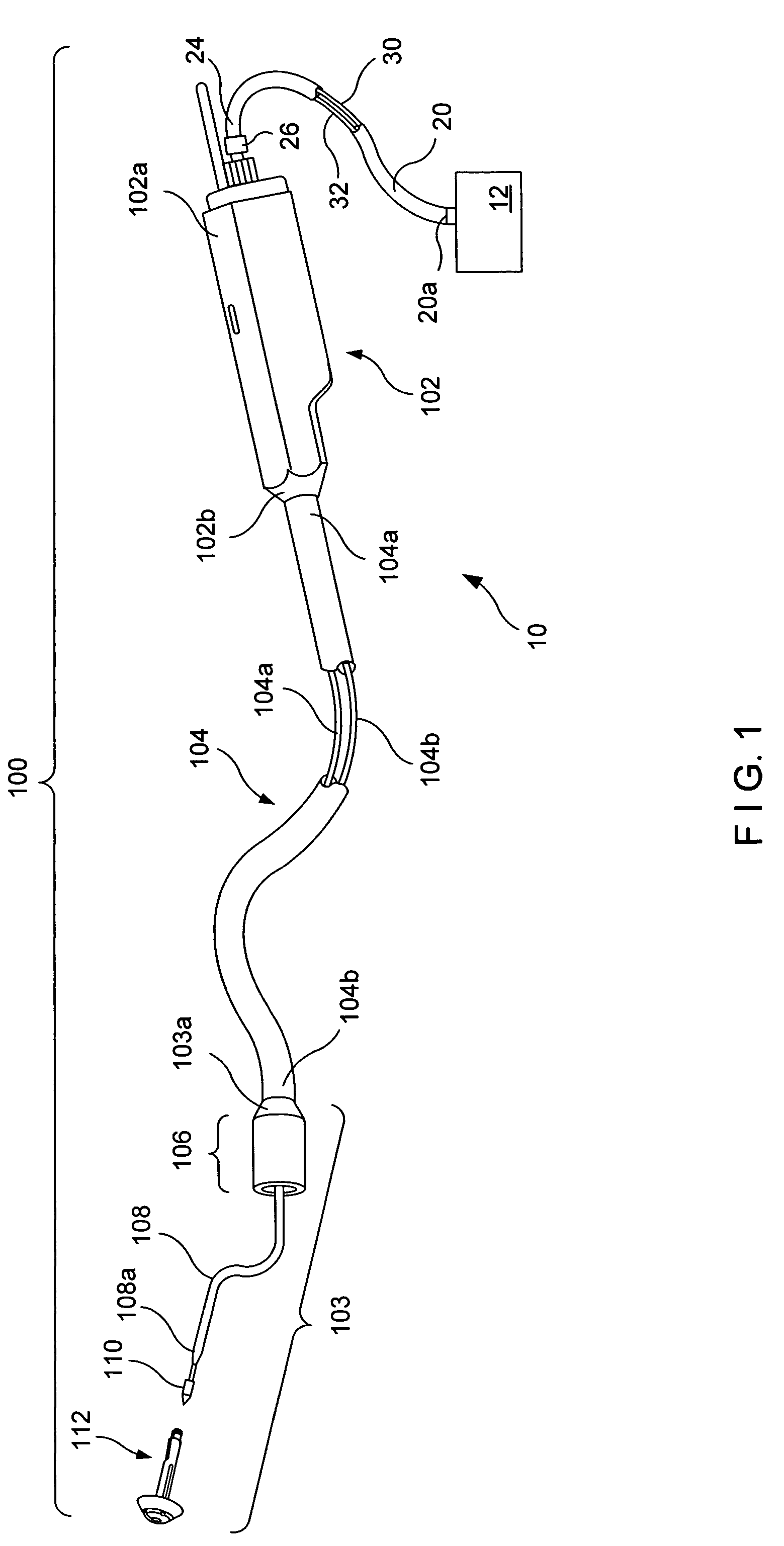
[0058]The present invention is directed to an electro-mechanical surgical system. FIG. 1 is a perspective view of an electromechanical surgical system 10 according to one embodiment of the present invention.
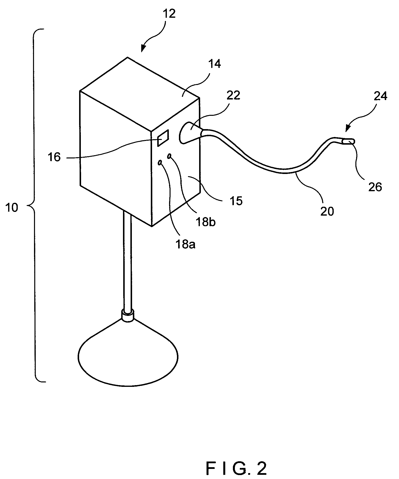
[0059]As shown in FIG. 1, the electro-mechanical surgical system 10 includes a remote power console 12 having a flexible shaft 20 extending therefrom. The flexible shaft 20 includes at least a first rotatable drive shaft 30 and a second rotatable drive shaft 32. Additional details of the remote power console 12 are described and shown in connection with, e.g., FIG. 2. Additional details of the flexible shaft 20 are described and shown in connection with, e.g., FIGS. 3 to 6.
[0060]Attached, or attachable, to a coupling 26 at the distal end 24 of the flexible cable 20 is a surgical attachment 100. The surgical attachment 100 is configured to perform a surgical operation. For the purposes of example only, the surgical attachments are described hereinbelow as being circular clamping, ...
PUM
Property
Measurement
Unit
distance
aaaaa
aaaaa
diameter
aaaaa
aaaaa
movement
aaaaa
aaaaa
Abstract
The present invention, in accordance with various embodiments thereof, relates to a surgical device for at least one of cutting and stapling a section of tissue. The surgical device includes a housing including at least two drivers. The surgical device also includes an anvil mechanically attachable to the housing and moveable relative to the housing between an open position and a closed position. The first driver operates to move the anvil relative to the housing to an intermediate position between the open position and the closed position. The second driver operates to move at least a portion of the housing relative to the anvil between the intermediate position and the closed position.
Description
CROSS-REFERENCE TO RELATED APPLICATIONS[0001]This application relates to U.S. patent application Ser. No. 09 / 324,452, filed on Jun. 2, 1999 and issued as U.S. Pat. No. 6,443,973, U.S. application Ser. No. 09 / 723,715, filed on Nov. 28, 2000, U.S. application Ser. No. 09 / 324,451, filed on Jun. 2, 1999 and issued as U.S. Pat. No. 6,315,184, U.S. application Ser. No. 09 / 351,534, filed on Jul. 12, 1999 and issued as U.S. Pat. No. 6,264,087, U.S. application Ser. No. 09 / 510,923, filed on Feb. 22, 2000 and issued as U.S. Pat. No. 6,517,565, U.S. application Ser. No. 09 / 510,927, filed on Feb. 22, 2000, U.S. application Ser. No. 09 / 510,932, filed on Feb. 22, 2000 and issued as U.S. Pat. No. 6,491,201, U.S. application Ser. No. 09 / 836,781, filed on Apr. 17, 2001, U.S. patent application Ser. No. 09 / 887,789, filed on Jul. 22, 2001, each of which is expressly incorporated herein in its entirety by reference.FIELD OF THE INVENTION[0002]The present invention relates to an electromechanical surgic...
Claims
Application Information
Patent Timeline
Application Date:The date an application was filed.
Publication Date:The date a patent or application was officially published.
First Publication Date:The earliest publication date of a patent with the same application number.
Issue Date:Publication date of the patent grant document.
PCT Entry Date:The Entry date of PCT National Phase.
Estimated Expiry Date:The statutory expiry date of a patent right according to the Patent Law, and it is the longest term of protection that the patent right can achieve without the termination of the patent right due to other reasons(Term extension factor has been taken into account ).
Invalid Date:Actual expiry date is based on effective date or publication date of legal transaction data of invalid patent.