Light emitting diode driving circuit and light emitting diode array device

a technology of light emitting diodes and driving circuits, which is applied in the direction of lighting and heating apparatus, process and machine control, instruments, etc., can solve the problems of reducing the efficiency and reliability of the product, increasing the cost and size of the product, and degrading the electromagnetic interference characteristics

Active Publication Date: 2011-09-27
SAMSUNG ELECTRONICS CO LTD
View PDF22 Cites 7 Cited by
  • Summary
  • Abstract
  • Description
  • Claims
  • Application Information

AI Technical Summary

Problems solved by technology

However, such an additional circuit complicates configuration of an LED module and furthermore potentially undermines efficiency and reliability when a supply power source is converted.
Moreover, the additional part other than the light source increases costs and size of the product and also degrades electromagnetic interference (EMI) characteristics due to a periodic component when operating in the switching mode.
But the conventional arrangement of LEDs ensures very low efficiency.
That is, a greater number of LEDs are inefficiently required to attain desired emission.

Method used


Image

  • Light emitting diode driving circuit and light emitting diode array device
  • Light emitting diode driving circuit and light emitting diode array device
  • Light emitting diode driving circuit and light emitting diode array device

Examples


Embodiment Construction

[0027]Exemplary embodiments of the present invention will now be described in detail with reference to the accompanying drawings.

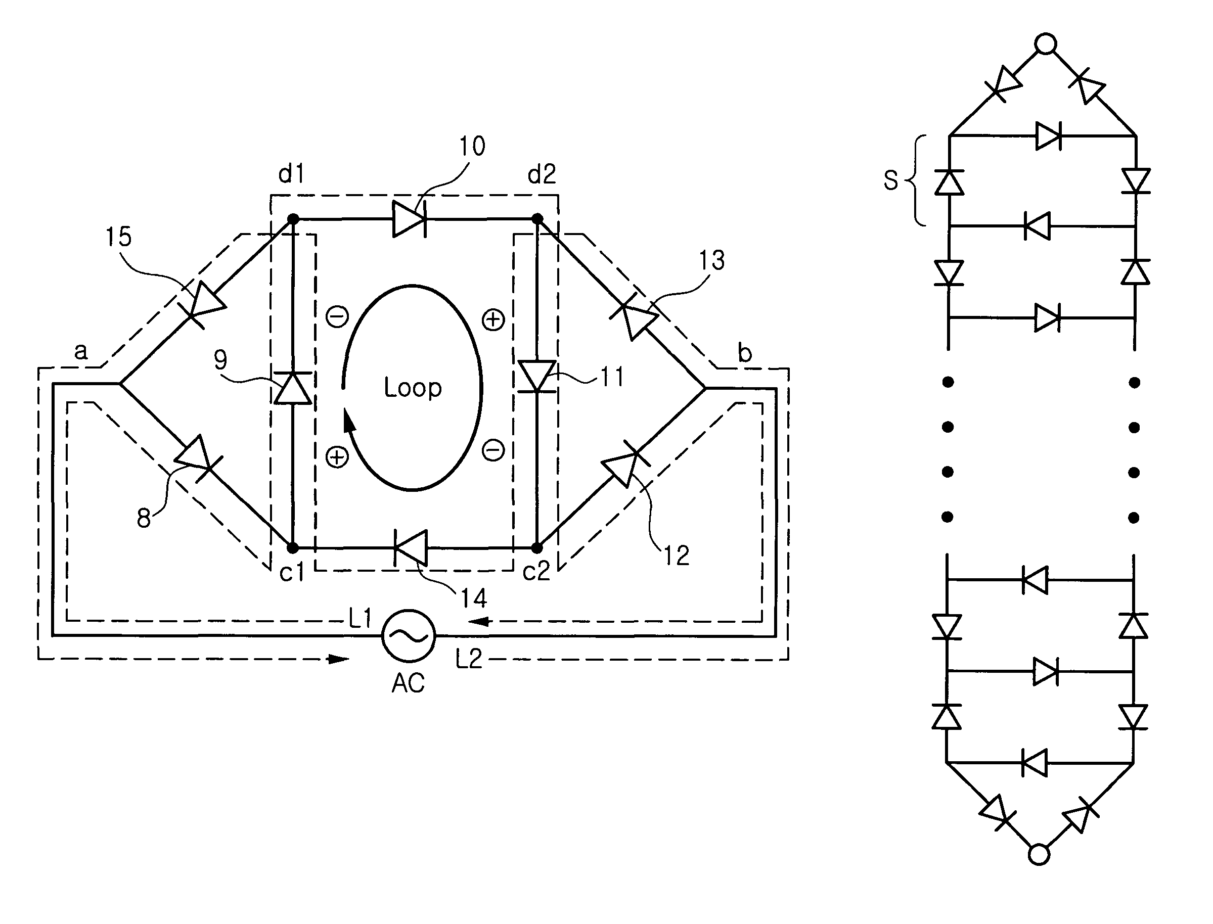
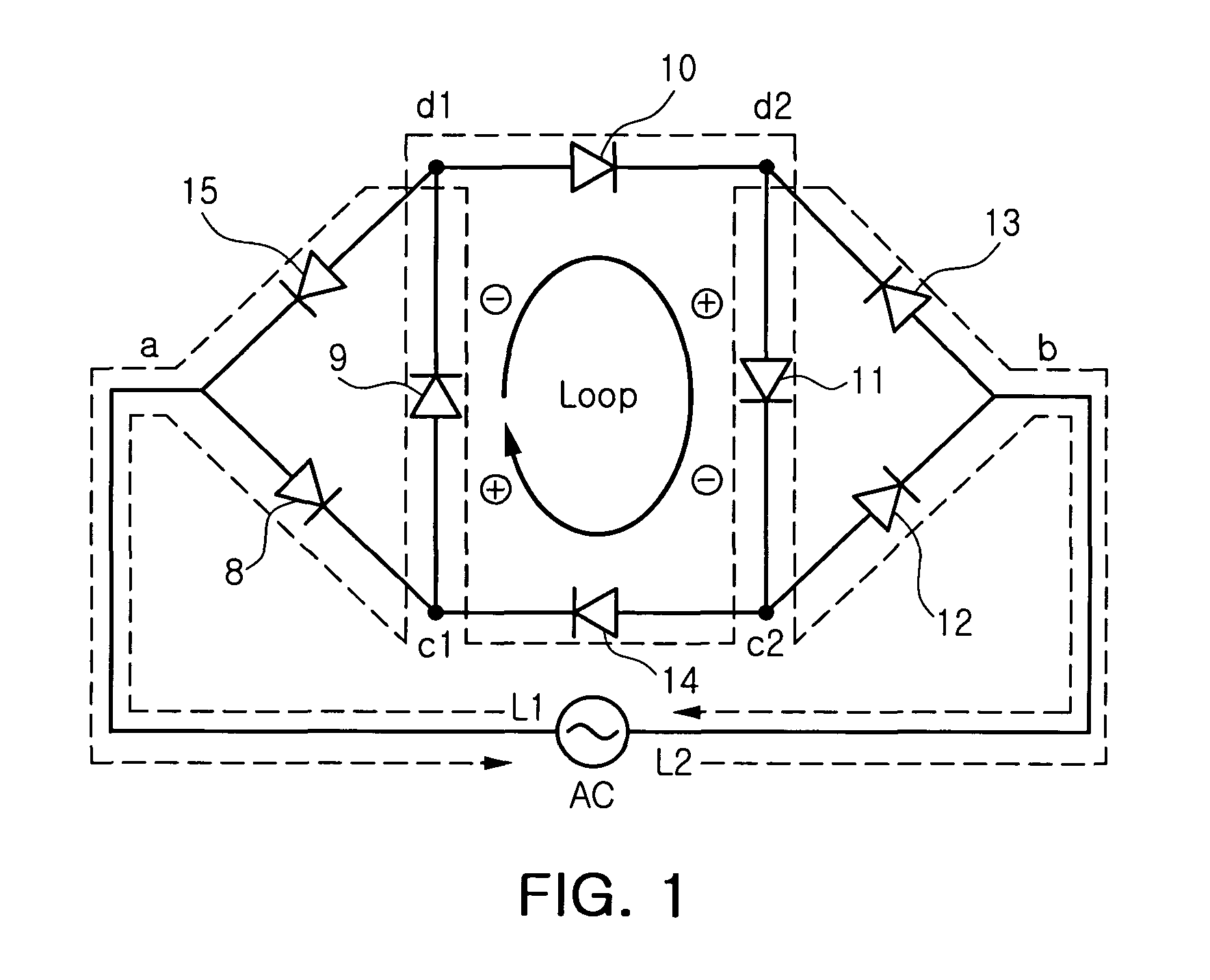
[0028]FIG. 1 illustrates a light emitting diode (LED) driving circuit according to an exemplary embodiment of the invention.

[0029]The LED driving circuit includes a ladder network LED circuit. That is, the ladder network LED circuit of the present embodiment includes three first branches connected to one another by first middle junction points c1 and c2 between first and second junction points a and b, and three second branches connected to one another by second middle junction points d1 and d2 between the first and second junction points a and b. The LED driving circuit includes two middle branches connected between the first and second middle junction points c1, d1, c2 and d2 of an identical sequence. Here, LED devices 8, 9, 10, 11, 12, 13, 14, and 15 are disposed on the first and second branches and the middle branches, respectively.

[0030]The LED drivin...


PUM


Abstract

There is provided an LED driving circuit including: at least one ladder network circuit including: (n+1) number of first branches connected in parallel with one another by n number of first middle junction points between a first junction point and a second junction point, where n denotes an integer satisfying n≧2, (n+1) number of second branches connected in parallel with one another by n number of second middle junction points between the first junction point and the second junction point, the (n+1) number of second branches connected in parallel with the first branches; and n number of middle branches connecting the first and second middle junction points of an identical m sequence to each other, respectively, wherein each of the first and second, and middle branches comprises at least one LED device.

Description

CROSS-REFERENCE TO RELATED APPLICATIONS[0001]This application claims the priority of Korean Patent Application No. 2007-61593 filed on Jun. 22, 2007, in the Korean Intellectual Property Office, the disclosure of which is incorporated herein by reference.BACKGROUND OF THE INVENTION[0002]1. Field of the Invention[0003]The present invention relates to a light emitting diode (LED) circuit, and more particularly, to an LED driving circuit directly applicable to an alternating current (AC) power without requiring a converter for converting the AC into a direct current (DC), and an LED array apparatus.[0004]2. Description of the Related Art[0005]A semiconductor light emitting diode (LED) is advantageous as a light source in terms of output, efficiency or reliability. Thus, the LED is actively researched and developed as a high-output and high efficiency light source to substitute a backlight of a lighting device or a display device.[0006]In general, the LED is driven in a low driving curre...

Claims


Application Information

Patent Timeline
Patent Type & Authority Patents(United States)
IPC IPC(8): H05B37/02H01L33/00H05B44/00
CPCH05B33/0803H05B33/0821Y10S362/808Y10S362/80Y02B20/342H05B45/00H05B45/42Y02B20/30
Inventor LEE, YOUNG JINMIN, BYOUNG OWNPARK, GIL HANONUSHKIN, GRIGORY
Owner SAMSUNG ELECTRONICS CO LTD
Why Eureka
Try Eureka