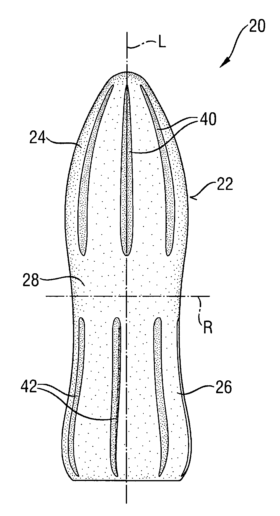
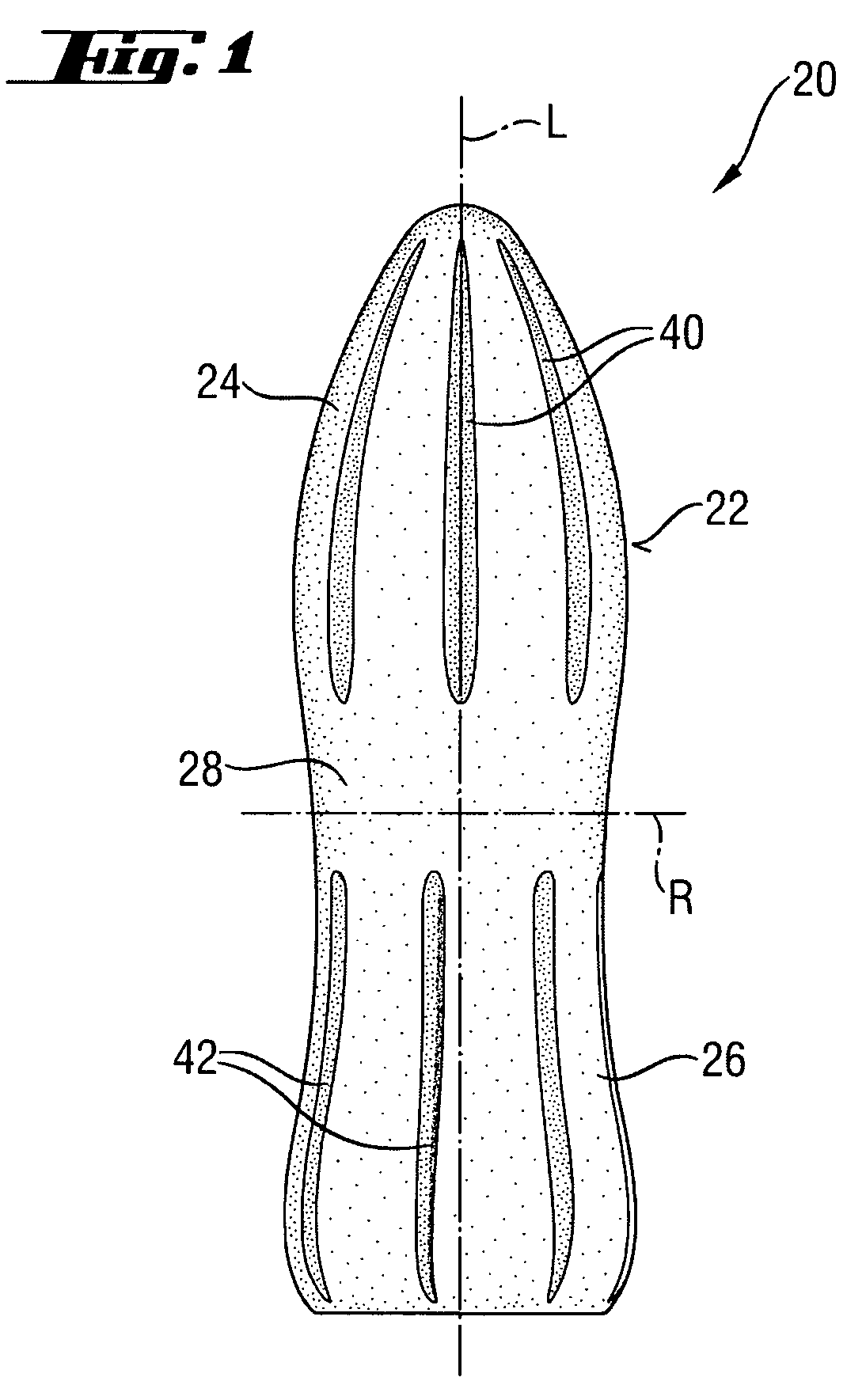
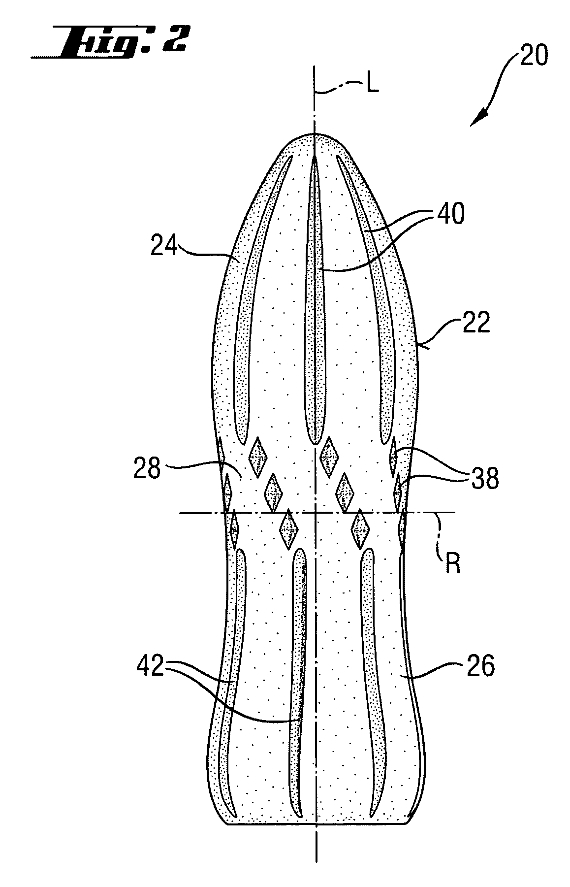
Tampon with offset grooves

a technology of offset grooves and tampons, which is applied in the field of tampons comprising offset longitudinal grooves, can solve the problems of not always supplying sufficient menstrual fluid to provide good coverag

Inactive Publication Date: 2011-10-04
PROCTER & GAMBLE CO
View PDF41 Cites 32 Cited by
  • Summary
  • Abstract
  • Description
  • Claims
  • Application Information

AI Technical Summary

Problems solved by technology

While it has been found that these tampons perform their intended function tolerably well, even the best of them do not always imbibe menstrual fluid at a rate sufficient to provide good coverage against leakage.

Method used


Image

  • Tampon with offset grooves
  • Tampon with offset grooves
  • Tampon with offset grooves

Examples


Embodiment Construction

[0007]As used herein “applicator” refers to a device or implement that facilitates the insertion of a tampon, medicament, treatment device, visualization aid, or other into an external orifice of a mammal, such as the vagina, rectum, ear canal, nasal canal, or throat. Non-limiting specific examples of such include any known hygienically designed applicator that is capable of receiving a tampon may be used for insertion of a tampon, including the so-called telescoping, tube and plunger, and the compact applicators, an applicator for providing medicament to an area for prophylaxis or treatment of disease, a spectroscope containing a microcamera in the tip connected via fiber optics, a speculum of any design, a tongue depressor, a tube for examining the ear canal, a narrow hollow pipe for guiding surgical instruments, and the like.

[0008]As used herein, the term “bicomponent fibers” refers to fibers that have been formed from at least two different polymers extruded from separate extrud...


PUM


Abstract

A tampon for feminine hygiene that has an insertion end, a withdrawal end, a central portion between the insertion end and the withdrawal end, a length, a longitudinal axis, a radial axis, and an outer surface. The tampon is made of compressed fibrous material. The outer surface of the insertion end has a plurality of longitudinal grooves which are offset from the plurality of longitudinal grooves located in the withdrawal end.

Description

CROSS REFERENCE TO RELATED APPLICATIONS[0001]This application claims priority to European Patent Application 04002551.2, filed Feb. 5, 2004, pending.FIELD OF THE INVENTION[0002]This invention relates to a tampon comprising offset longitudinal grooves.BACKGROUND OF THE INVENTION[0003]A wide variety of absorbent catamenial tampons have long been known in the art. It is known that the surface characteristics of a tampon may be altered physically and / or chemically to confer both aesthetic and functional benefits. The surface of tampons can be altered to have non-uniform surface topography. Some examples of tampons with non-uniform topography include a tampon that has absorbent filaments such as in U.S. Pat. No. 3,695,270 issued to Dostal on Oct. 3, 1972, and a tampon with a braided or rope shaped body such as in U.S. Pat. No. 4,361,151 issued to Fitzgerald on Nov. 20, 1982 and U.S. Pat. No. 4,328,804 issued to Shimatani on May 11, 1982. Other tampons comprise longitudinal ribs on the ou...

Claims


Application Information

Patent Timeline
Patent Type & Authority Patents(United States)
IPC IPC(8): A61F13/20
CPCA61F13/2051
Inventor JENSEN, TIM
Owner PROCTER & GAMBLE CO
Why Eureka
Try Eureka