
Orifice insertion devices and methods

a technology of orifice and insertion device, which is applied in the field of orifice sealing, can solve problems such as proper fitting

Active Publication Date: 2011-11-01
STATON TECHIYA LLC
View PDF26 Cites 74 Cited by
  • Summary
  • Abstract
  • Description
  • Claims
  • Application Information

AI Technical Summary

Benefits of technology

The solution ensures a secure seal across various orifice sizes, enhancing sound isolation and comfort by dynamically adjusting to fit different dimensions, thereby improving the fit and performance of earpieces and other acoustic devices.

Problems solved by technology

However fitting properly is a problem with current systems.

Method used


Image

  • Orifice insertion devices and methods
  • Orifice insertion devices and methods
  • Orifice insertion devices and methods

Examples


Embodiment Construction

[0015]The following description of exemplary embodiment(s) is merely illustrative in nature and is in no way intended to limit the invention, its application, or uses.

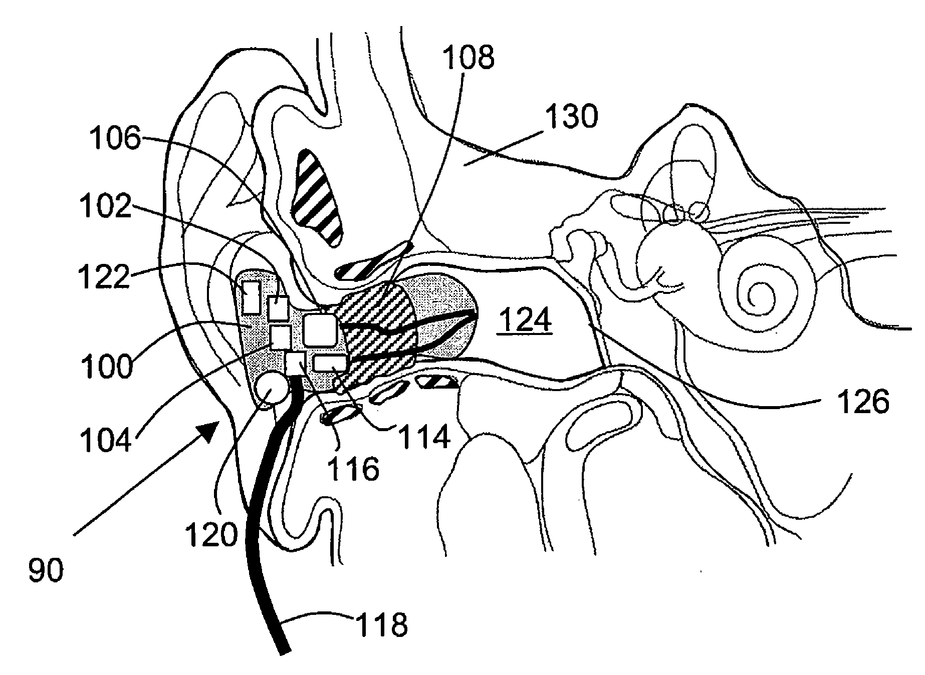
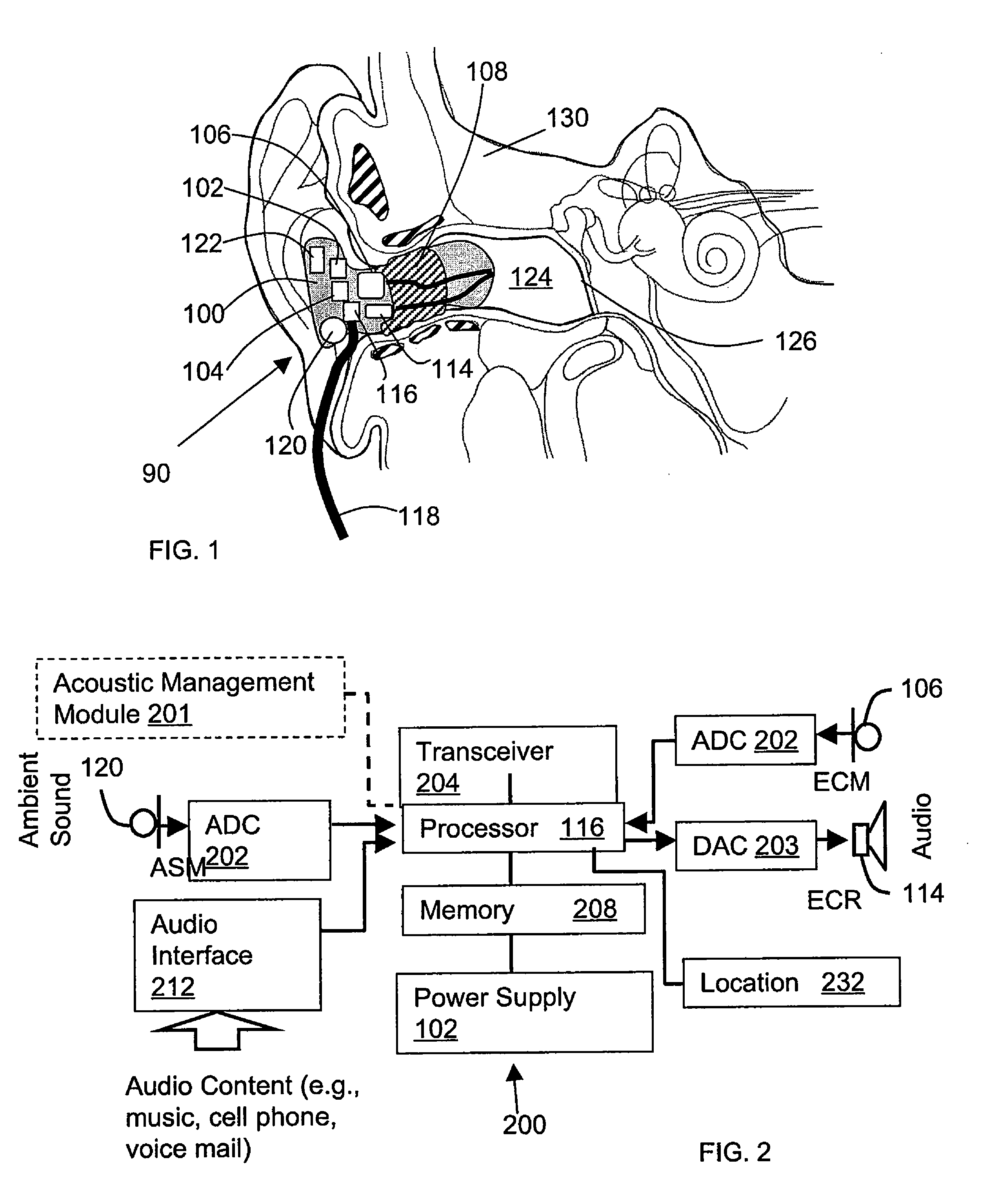
[0016]Exemplary embodiments are directed to or can be operatively used on various orifice insertion devices, wired or wireless (e.g., earbuds, headphones, ear terminals, behind the ear devices, nasal inserts, anal, vein and artery inserts or other such devices as known by one of ordinary skill, and equivalents).

[0017]Processes, techniques, apparatus, and materials as known by one of ordinary skill in the art may not be discussed in detail but are intended to be part of the enabling description where appropriate. For example specific computer code may not be listed for achieving each of the steps discussed, however one of ordinary skill would be able, without undo experimentation, to write such code given the enabling disclosure herein. Such code is intended to fall within the scope of at least one exemplary embodiment....


PUM


Abstract

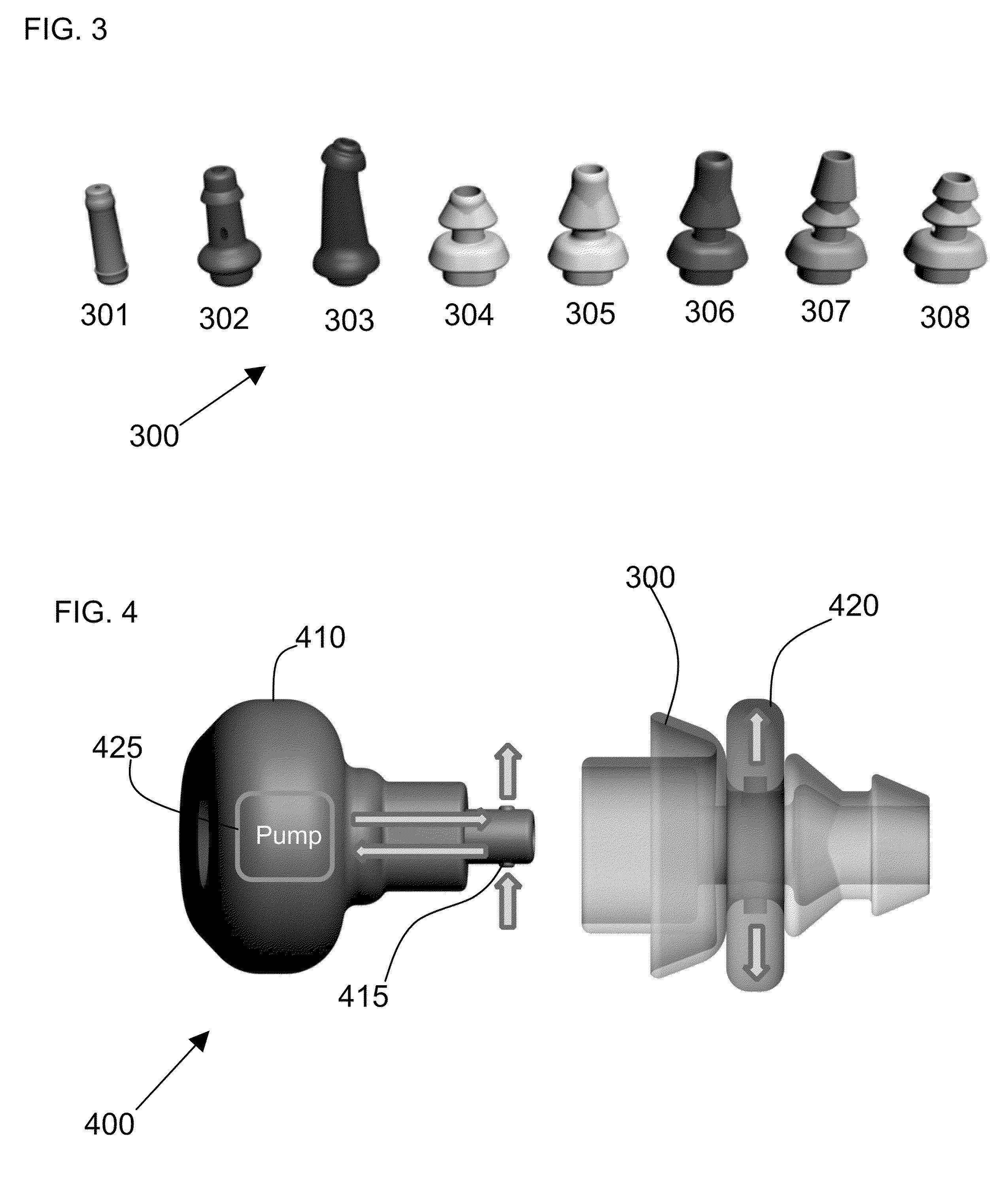
Methods and devices for sealing an orifice are provided. A sealing element is inserted into an orifice. A fluid is transferred into the sealing element. Fluid transfer into the sealing element is restricted when a pressure in the sealing element is greater than a threshold value.

Description

CROSS-REFERENCE TO RELATED APPLICATIONS[0001]This application claims the benefit of U.S. provisional patent application No. 60 / 957,177 filed on 22 Aug. 2007. The disclosure of which is incorporated herein by reference in its entirety.FIELD OF THE INVENTION[0002]The present invention relates to orifice sealing, and more particularly, though not exclusively, to inflatable and other sealing configurations of earpieces.BACKGROUND OF THE INVENTION[0003]Contemporary earpieces and orifice sealing devices utilize foam and / or flexible low durometer material, which can provide sound isolation if fitted properly. However fitting properly is a problem with current systems. A system that can expand or contract to fit most orifices (e.g., ear canals, nose, veins, pipes) would be useful.SUMMARY OF THE INVENTION[0004]In one embodiment, the invention provides a method of sealing an orifice wherein a sealing element is inserted into the orifice. A fluid is transferred into the sealing element. Fluid ...

Claims


Application Information

Patent Timeline
Patent Type & Authority Patents(United States)
IPC IPC(8): A61F11/00H04R25/00A61B7/02H04R25/02
CPCA61F11/10H04R25/652H04R25/656
Inventor PEREZ, MOISESKEADY, JOHN PATRICK
Owner STATON TECHIYA LLC
Learn More