
Low sound attenuating hearing protection device with filter arrangement

a filter arrangement and low sound attenuation technology, applied in the field of hearing protection devices, can solve the problems of reducing the attenuation, near a complete attenuation of sound, and the low sound attenuation provided by many common earplugs

Active Publication Date: 2011-11-08
3M INNOVATIVE PROPERTIES CO
View PDF16 Cites 28 Cited by
  • Summary
  • Abstract
  • Description
  • Claims
  • Application Information

AI Technical Summary

Benefits of technology

The invention is a hearing protection device that includes a sound attenuating portion, a channel, a tube, and a filter. The sound attenuating portion is placed in the ear canal to block the passage of sound. The channel is formed through the sound attenuating portion to allow sound to pass through. The tube is placed in the channel to allow the sound to pass through. The filter is placed at one end of the tube and inside the sound attenuating portion. The filter attenuates some of the sound passing through the tube. The invention also provides a method for manufacturing the hearing protection device. The technical effects of the invention are that it provides effective hearing protection against loud sounds and offers a comfortable fit in the ear canal.

Problems solved by technology

Where a proper fit of the device is obtained, in many cases, nearly a complete attenuation of sound results.
In such an instance, full or nearly full sound attenuation provided by many common earplugs is not desirable.
Some previous attempts in this range have resulted in decreased attenuation at moderate and higher frequencies but, at lower frequencies, did not provide sufficient attenuation.
Some hearing protection devices have been developed which can provide reduced attenuation over a broad range of frequencies but require expensive filters, damping elements, and / or electronic arrangements and are complicated to manufacture and assemble.

Method used


Image

  • Low sound attenuating hearing protection device with filter arrangement
  • Low sound attenuating hearing protection device with filter arrangement
  • Low sound attenuating hearing protection device with filter arrangement

Examples


Embodiment Construction

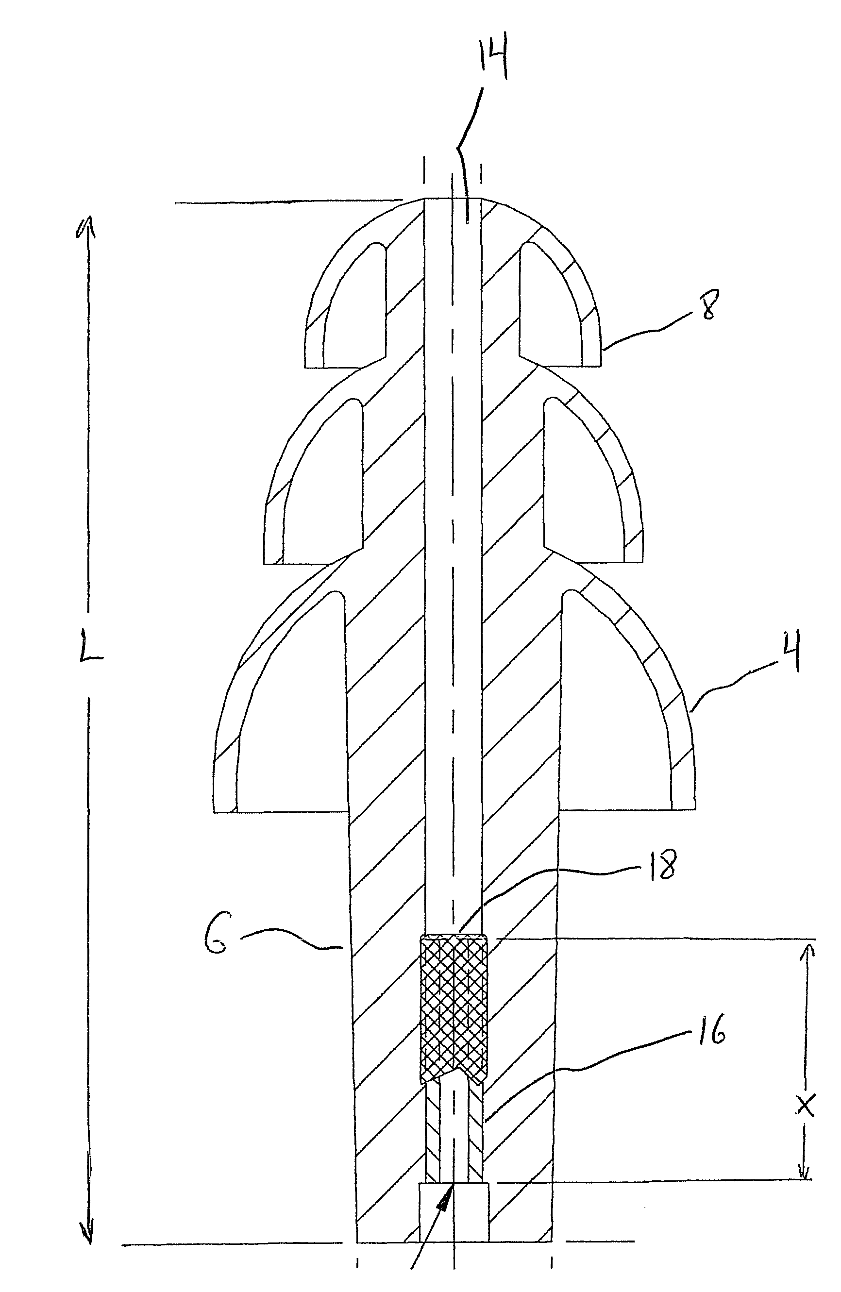
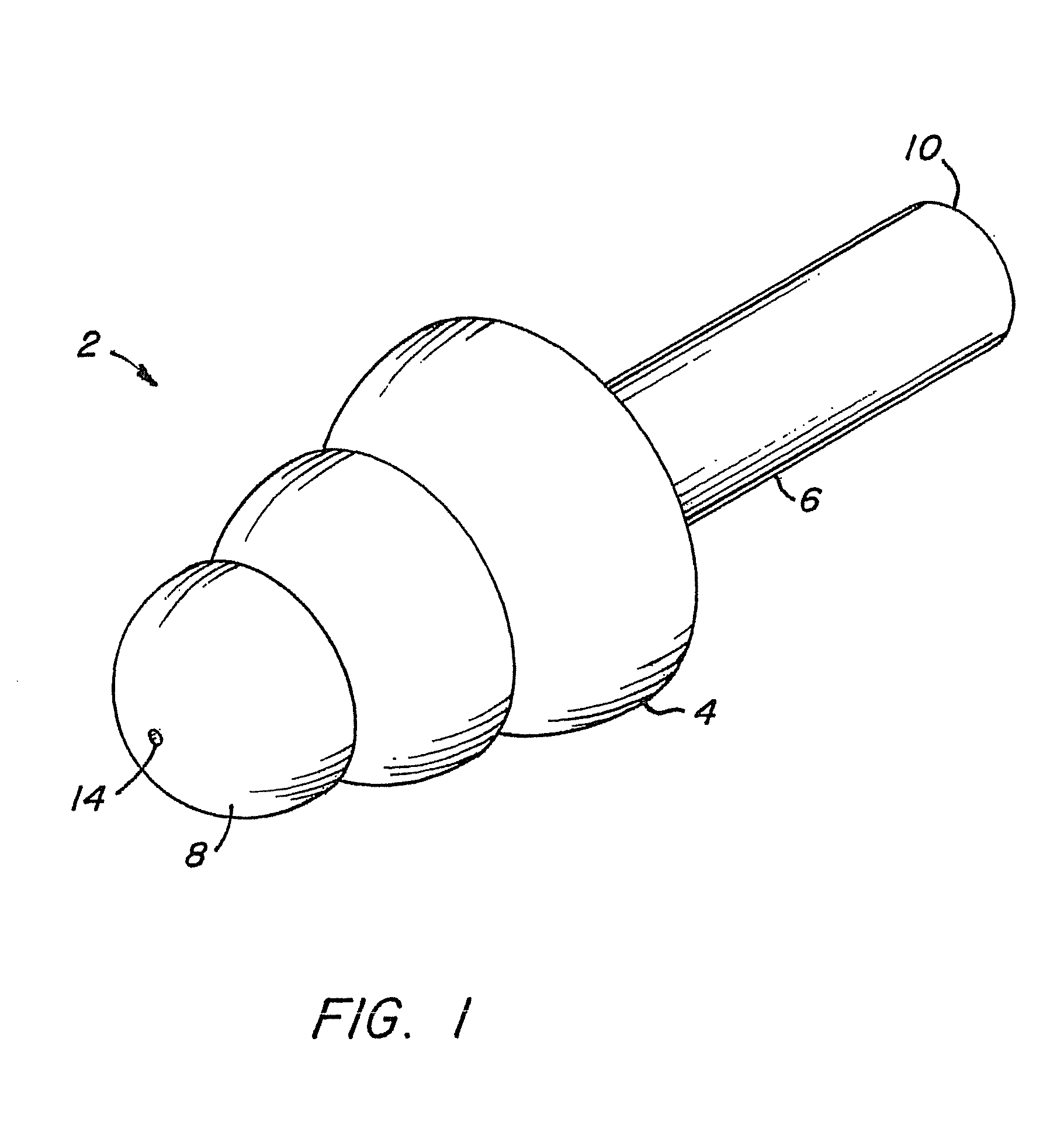
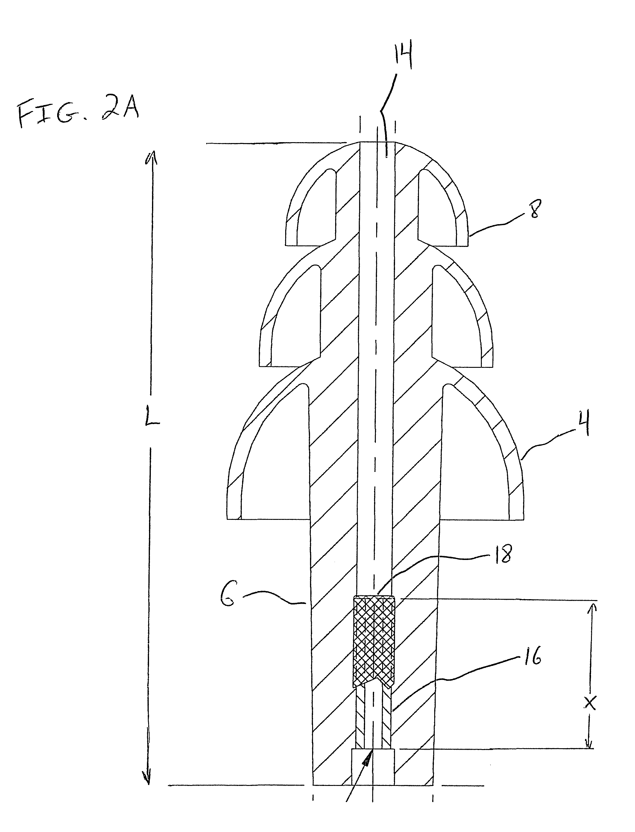
[0033]FIGS. 1-3 show a hearing protection device in one embodiment of the invention. Particularly, an earplug 2 is shown including flanges 4 emanating from an elongated stalk member 6. The stalk member 6 has a first end 8 from which a first of the flanges 4 emanates and an opposing second end 10 which extends longitudinally beyond the flanges 4. The flanges 4 are substantially hemispherical in shape and extend in a direction toward the second end 10 of the stalk member 6 such that spaces 12 are formed between a back side of the flanges 4 and the stalk member 6. Each of the plurality of flanges 4 includes a semi-substantially circular cross-section A. The flanges 4 are variously sized such that the cross-section A of the flange 4 proximate the first end 8 of the stalk member 6 is the smallest with each successive flange 4 having a larger cross-section A.

[0034]The stalk member 6 further includes a channel 14 formed therethrough along a longitudinal axis of the earplug 2. That is, the ...


PUM


Abstract

A hearing protection device including a sound attenuating portion configured to be disposed within an ear canal of a user to obstruct a passage of sound, a channel formed through the sound attenuating portion configured to allow sound to pass through the sound attenuating portion when the portion is disposed within the ear canal, a tube disposed in the channel and configured to allow the sound in the channel to pass therethrough, and a filter disposed at one end of the tube and positioned at an interior of the sound attenuating portion, where the filter attenuates some of the sound passing through the tube.

Description

CROSS REFERENCE TO RELATED APPLICATION[0001]This application is a continuation-in-part of U.S. patent application Ser. No. 10 / 700,213 filed on 3 Nov. 2003 now U.S. Pat. No. 7,697,706, the contents of which are herein incorporated by reference in their entirety.TECHNICAL FIELD OF INVENTION[0002]The invention concerns hearing protection devices and, more particularly, hearing protection devices which provide a low or relatively reduced sound attenuation.DESCRIPTION OF RELATED ART[0003]Hearing protection devices, such as earplugs and semi-aural devices, are readily used to provide sound attenuation. Such devices are inserted into the ear canal of a user, or placed over the opening of the ear canal, to physically obstruct the passage of sound waves into the inner ear.[0004]Earplugs include any of a variety of devices designed to be inserted in the ear canal of a user and worn therein to prevent sounds from entering. Push-in type earplugs comprise an attenuating portion and a rigid or se...

Claims


Application Information

Patent Timeline
Patent Type & Authority Patents(United States)
IPC IPC(8): A61F11/06H04R25/00A61F11/08A61F11/12
CPCA61F11/08A61F11/12A61F2011/085A61F11/085
Inventor DOTY, MARC L.
Owner 3M INNOVATIVE PROPERTIES CO
Learn More