Supercharge Your Innovation With Domain-Expert AI Agents!

Antifuse structures, antifuse array structures, methods of manufacturing the same

a technology of array structure and antifuse, applied in the field of antifuse structure, can solve the problems of reducing, needing to be discarded, and memory device of the semiconductor memory device may not function properly, etc., and achieve the effect of simple antifuse structur

Active Publication Date: 2011-11-15
SAMSUNG ELECTRONICS CO LTD
View PDF6 Cites 0 Cited by
  • Summary
  • Abstract
  • Description
  • Claims
  • Application Information

AI Technical Summary

Benefits of technology

This configuration simplifies the antifuse structure, allowing for concurrent selection and operation of all cells, improving integration density and reducing the need for high driving voltages, thus enhancing semiconductor device yield and integration capabilities.

Problems solved by technology

If even one of the cells is defective, the semiconductor memory device may not function properly.
If the semiconductor memory device does not function properly, it may need to be discarded.
This may reduce (e.g., severely reduce) product yield.
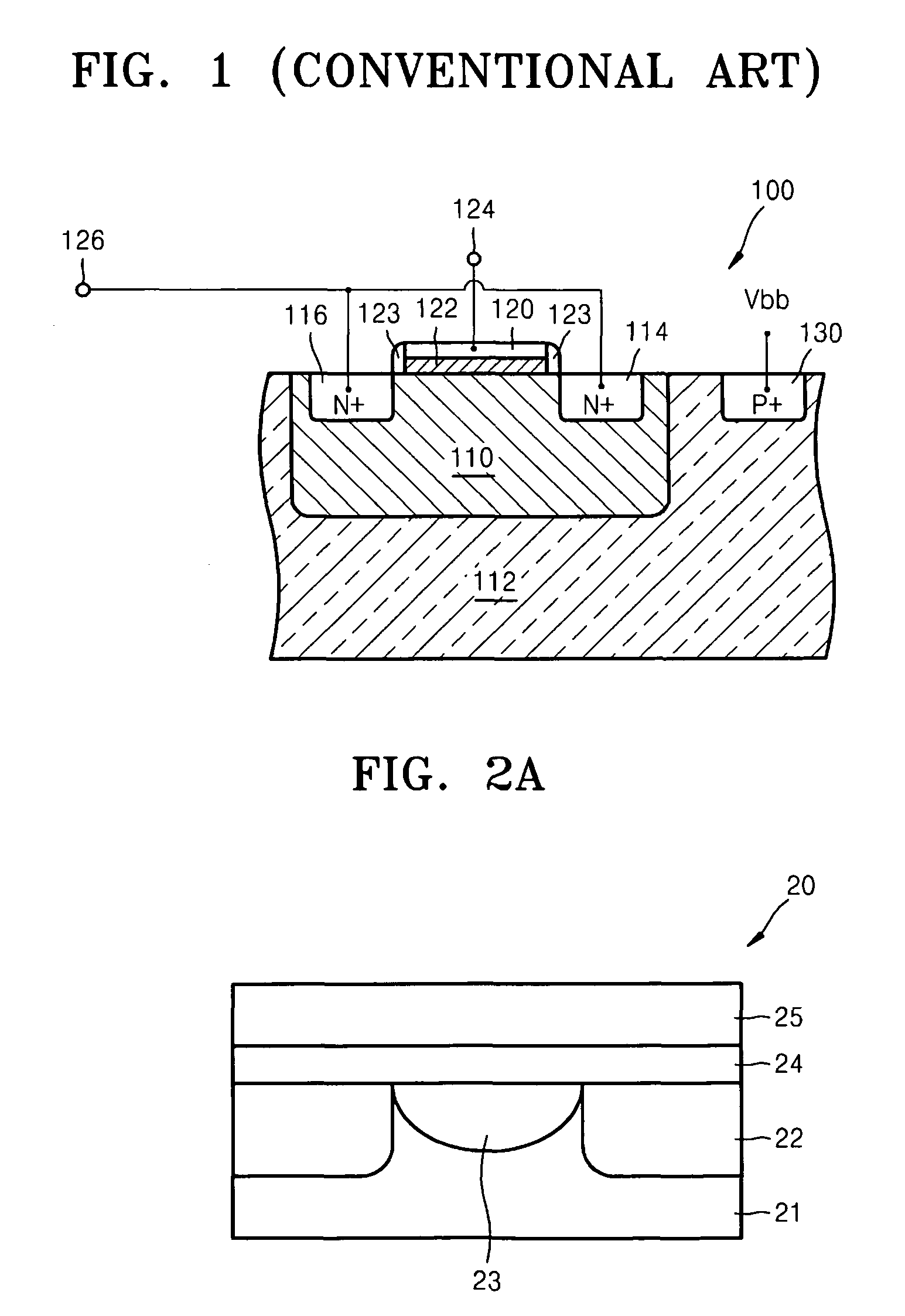
However, if the structure shown in FIG. 1 is arranged in an array, the array structure may require a relatively large area or region and / or require a relatively high driving voltage.
Accordingly, increasing integration of a semiconductor device may be relatively difficult.

Method used


Image

  • Antifuse structures, antifuse array structures, methods of manufacturing the same
  • Antifuse structures, antifuse array structures, methods of manufacturing the same
  • Antifuse structures, antifuse array structures, methods of manufacturing the same

Examples


Embodiment Construction

[0030]Various example embodiments will now be described more fully with reference to the accompanying drawings in which some example embodiments are shown. In the drawings, the thicknesses of layers and regions are exaggerated for clarity.

[0031]Detailed illustrative example embodiments are disclosed herein. However, specific structural and functional details disclosed herein are merely representative for purposes of describing example embodiments. This invention may, however, may be embodied in many alternate forms and should not be construed as limited to only the example embodiments set forth herein.

[0032]Accordingly, while example embodiments are capable of various modifications and alternative forms, embodiments thereof are shown by way of example in the drawings and will herein be described in detail. It should be understood, however, that there is no intent to limit example embodiments to the particular forms disclosed, but on the contrary, example embodiments are to cover all...


PUM


Abstract

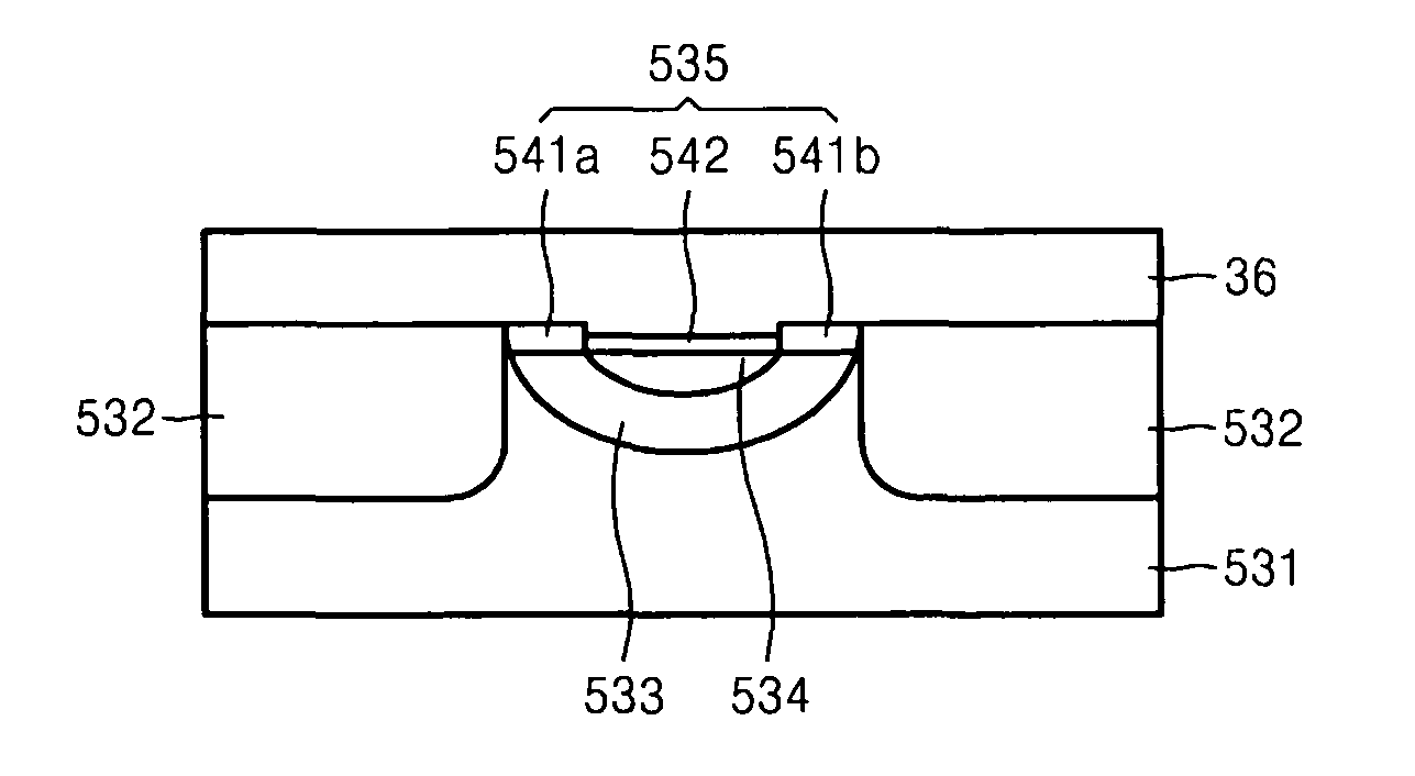
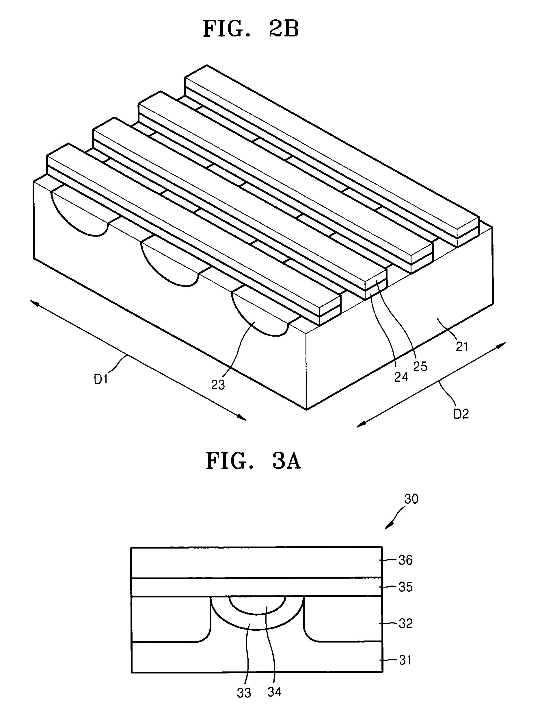
Antifuse structures, antifuse arrays, methods of manufacturing, and methods of operating the same are provided. An antifuse structure includes bitlines formed as first diffusing regions within a semiconductor substrate, an insulation layer formed on the bitlines, and wordlines formed on the insulation layer. An antifuse array includes a plurality of antifuse structures arranged in an array.

Description

PRIORITY STATEMENT[0001]This non-provisional patent application claims priority under 35 U.S.C. §119 to Korean Patent Application No. 10-2007-0104060, filed on Oct. 16, 2007, in the Korean Intellectual Property Office, the entire contents of which is incorporated herein by reference.BACKGROUNDDescription of the Related Art[0002]Conventional semiconductor devices, for example, a conventional semiconductor memory device, may include a relatively large number of cells. If even one of the cells is defective, the semiconductor memory device may not function properly. If the semiconductor memory device does not function properly, it may need to be discarded. This may reduce (e.g., severely reduce) product yield.[0003]To assist in improving product yield, conventional semiconductor memory devices may include a plurality of redundancy cells (e.g., pre-formed redundancy cells) for replacing defective cells. The plurality of redundancy cells may comprise a plurality of spare rows and a plural...

Claims


Application Information

Patent Timeline
Patent Type & Authority Patents(United States)
IPC IPC(8): H01L23/52
CPCH01L23/5252H01L27/1021G11C17/16H01L2924/0002H01L2924/00H10B20/25
Inventor KIM, DEOK-KEEPARK, YOON-DONGLEE, SEUNG-HOONSONG, I-HUNKIM, WON-JOOJIN, YOUNG-GUCHOI, HYUK-SOONKIM, SUK-PIL
Owner SAMSUNG ELECTRONICS CO LTD
Features
  • R&D
  • Intellectual Property
  • Life Sciences
  • Materials
  • Tech Scout
  • Unparalleled Data Quality
  • Higher Quality Content
  • 60% Fewer Hallucinations
Learn More