Carabiner with pivoting gate equipped with a locking ring

a technology of locking ring and pivoting gate, which is applied in the field of carabiners, can solve the problems of hammer sliding of the rope inside the body, and achieve the effect of limiting the risk of catching on the rop

Inactive Publication Date: 2011-11-22
ZEDEL CORP
View PDF11 Cites 36 Cited by
  • Summary
  • Abstract
  • Description
  • Claims
  • Application Information

AI Technical Summary

Benefits of technology

[0006]The object of the invention consists in providing a carabiner with a locking ring, limiting any risk of catching on the rope when the gate is closed and locked.
[0009]The presence of the frustum-shaped end head avoids any offset with the internal profile of the carabiner and enables the rope to slide well inside the body when the gate is closed.

Problems solved by technology

The presence of this offset is liable to hamper sliding of the rope inside the body.

Method used


Image

  • Carabiner with pivoting gate equipped with a locking ring
  • Carabiner with pivoting gate equipped with a locking ring
  • Carabiner with pivoting gate equipped with a locking ring

Examples


Embodiment Construction

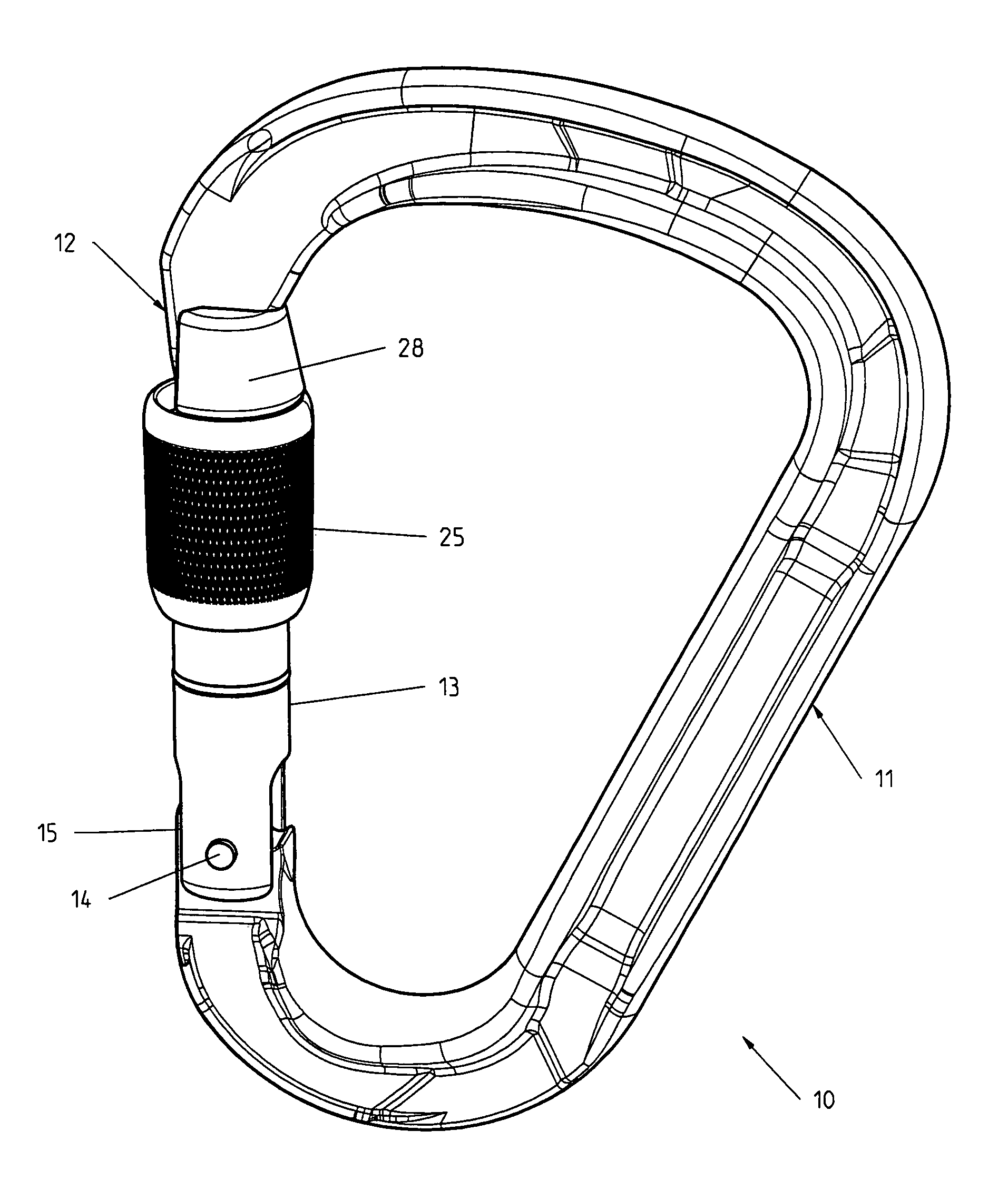
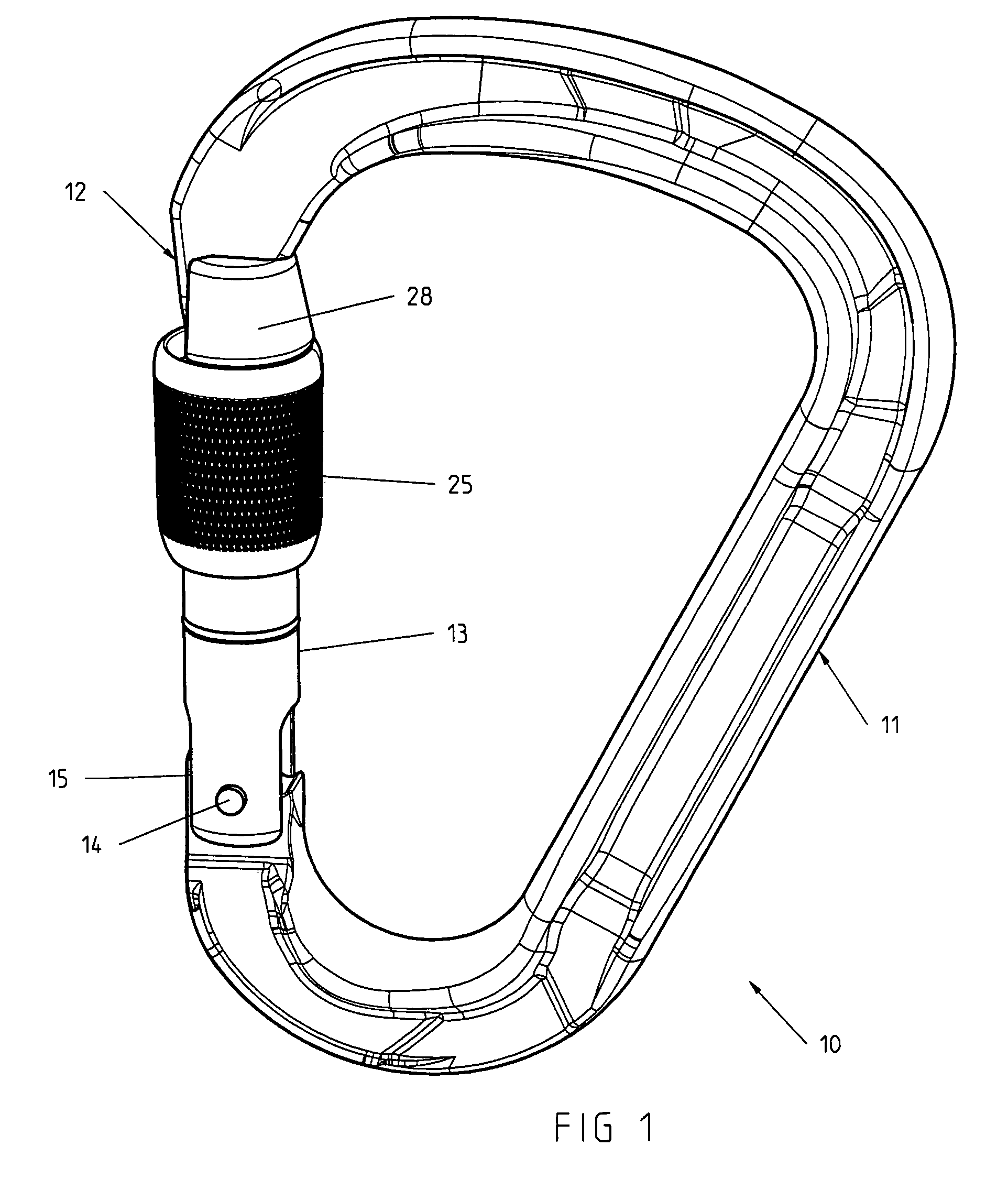
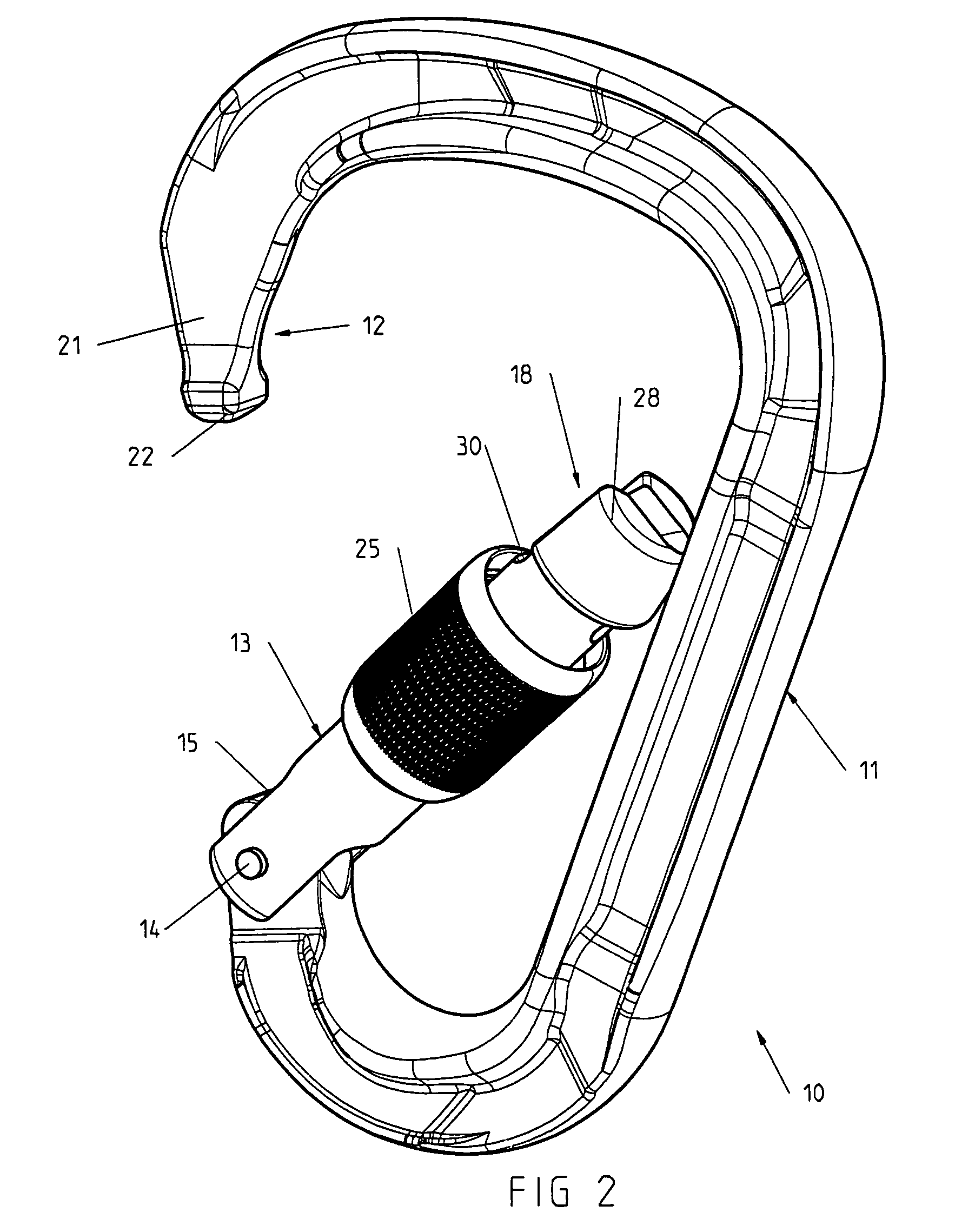
[0018]With reference to the figures, a carabiner 10 comprises a C-shaped metal body 11 having a first end provided with a male securing part 12 and a second end for articulation of a gate 13 movable around a pivoting axis 14 between a closed position (FIGS. 1 and 3) and an open position (FIG. 2).

[0019]Gate 13 comprises a metal bar comprising a reverse U-shaped cap 15 designed to cap the second end of the body 11, two orifices being drilled diametrically opposite holes 16, 17 in said cap for the pivoting axis 14 to pass. The opposite end of gate 13 is provided with a female latching part 18 designed to engage in male securing part 12 in the closed position. A return spring 19 is housed in a blind opening 20 of gate 13 on the same side as the axis 14 and biases gate 13 to the closed position.

[0020]Male securing part 12 of body 11 presents an inverted T-shaped structure comprising a tab 21 extended by a protuberance 22. Female latching part 18 of gate 13 comprises a recess 23 of conjug...


PUM


Abstract

A carabiner includes a fixed C-shaped body equipped with a securing part, and a gate movable around a pivoting axis between a closed position and an open position. The gate includes a latching part and a locking ring fitted coaxially around the gate. An end head of the gate partially surrounds the securing part in the closed position, and includes a shoulder acting as end-of-travel stop for the ring in the locked position.

Description

BACKGROUND OF THE INVENTION[0001]The invention relates to a carabiner comprising a fixed C-shaped body having a first end shaped as a securing part and a second end for articulation of a gate movable around a pivoting axis between a closed position and an open position, said gate comprising:[0002]a latching part situated opposite the pivoting axis to operate in conjunction with the securing part in the closed position,[0003]a return spring biasing the gate to the closed position,[0004]and a locking ring fitted coaxially around the gate and having a smaller length than that of the gate, said ring being movable between a first locked position enabling the gate to be locked in the closed position and a second unlocked position enabling the gate to be moved to the open position.STATE OF THE ART[0005]In a known carabiner of the kind mentioned, for example as described in the document DE 2536204, the movable gate is generally formed by a metal bar of cylindrical cross-section, and the coa...

Claims


Application Information

Patent Timeline
Patent Type & Authority Patents(United States)
IPC IPC(8): F16B45/02
CPCF16B45/02Y10T24/45435Y10T24/45361Y10T24/45366Y10T24/45408Y10T24/45372F16B45/026F16B45/023F16B45/005F16B45/027
Inventor PETZL, PAULCHOFFY, CHRISTOPHELANEZ, RAPHAEL
Owner ZEDEL CORP
Why Eureka
Try Eureka