Bit holder block with non-rotating wear sleeve

a technology of wear sleeves and bit holders, which is applied in the direction of earthwork drilling, cutting machines, etc., can solve the problems of affecting the useful life of cutting tools, affecting the use of cutting tools, and the rotational cutting tools and holders operate in a high wear environment, so as to prevent rotational movement, prevent the most of the abrasion, and easy manufacture anti-rotation

Inactive Publication Date: 2011-11-22
KENNAMETAL INC
View PDF33 Cites 27 Cited by
  • Summary
  • Abstract
  • Description
  • Claims
  • Application Information

AI Technical Summary

Benefits of technology

The present invention provides a block and non-rotating wear sleeve for holding a cutting tool used with mining and construction equipment. A key is used to intersect with notches in the wear sleeve and block at a rear face of the wear sleeve and block to prevent rotational movement between the components. Locating the key and notches at the rear face provides and easily manufactured anti-rotation means which is also sheltered from the most of the abrasion experienced by the block and wear sleeve.
An aspect of the present invention provides an apparatus for mounting a cutting tool used in mining and construction, comprising a block comprising a holder portion having an interior surface defining a bore disposed about a longitudinal axis and passing through the holder portion, the bore extending from front face of the holder portion to a rear face of the holder portion, and at least one slot in the rear face of the holder portion; a wear sleeve having a forward portion adjacent the front face of the holder portion and a shank extending through the bore of the holder portion, the shank having a rear end with at least one notch therein; at least one key engaging the at least one slot of the holder portion and the at least one notch of the shank of the wear sleeve, thereby preventing rotational movement of the wear sleeve relative to the holder portion; and means for retaining the wear sleeve in the holder portion.
Yet another aspect of the present invention provides an apparatus for mounting a cutting tool used in mining and construction, comprising a block comprising a holder portion having an interior surface defining a bore disposed about a longitudinal axis and passing through the holder portion, the bore extending from front face of the holder portion to a rear face of the holder portion; a wear sleeve having a forward portion adjacent the front face of the holder portion and a shank extending through the bore of the holder portion, the shank having a rear end; means for preventing rotation of the wear sleeve within the holder portion, wherein the means for preventing rotation is integrated into the rear face of the holder portion and the rear end of the shank of the wear sleeve; and means for retaining the wear sleeve in the holder portion.

Problems solved by technology

Rotatable cutting tools and the holders operate in a high wear environment.
These components inevitably fail due to the severity of the operating conditions; e.g. gritty, dusty and highly abrasive.
While it is expected that the cutting tools experience wear, the ability of the cutting tool to rotate about its central longitudinal axis during operation generally prolongs the useful life of the cutting tool.
Rotation promotes more even wear about the tool.
Although it is beneficial to promote rotation of the cutting tool, rotation of the wear sleeve in the bit holder is not desirable.
At the beginning of a milling cycle, the structure disclosed in U.S. Pat. No. 6,508,516 to Kammerer would be expected to provide a non-rotatable ring; however, over time the structure may be susceptible to problems.
One such problem is that the groove that engages the tab may become clogged with debris.
Obviously, this condition could compromise the integrity of the connection between the tab and the groove and result in the loss of the non-rotatable feature of the ring.
Another problem is that over the course of operation the tab is exposed along the side of the tool so as to be susceptible to wearing away.
The erosion of the tab could compromise the integrity of the connection between the tab and the groove and result in the loss of the non-rotatable feature of the ring.

Method used


Image

  • Bit holder block with non-rotating wear sleeve
  • Bit holder block with non-rotating wear sleeve
  • Bit holder block with non-rotating wear sleeve

Examples


Embodiment Construction

For purposes of the following detailed description, it is to be understood that the invention may assume various alternative variations and step sequences, except where expressly specified to the contrary. In this application, the use of the singular includes the plural and plural encompasses singular, unless specifically stated otherwise. In addition, in this application, the use of “or” means “and / or” unless specifically stated otherwise, even though “and / or” may be explicitly used in certain instances.

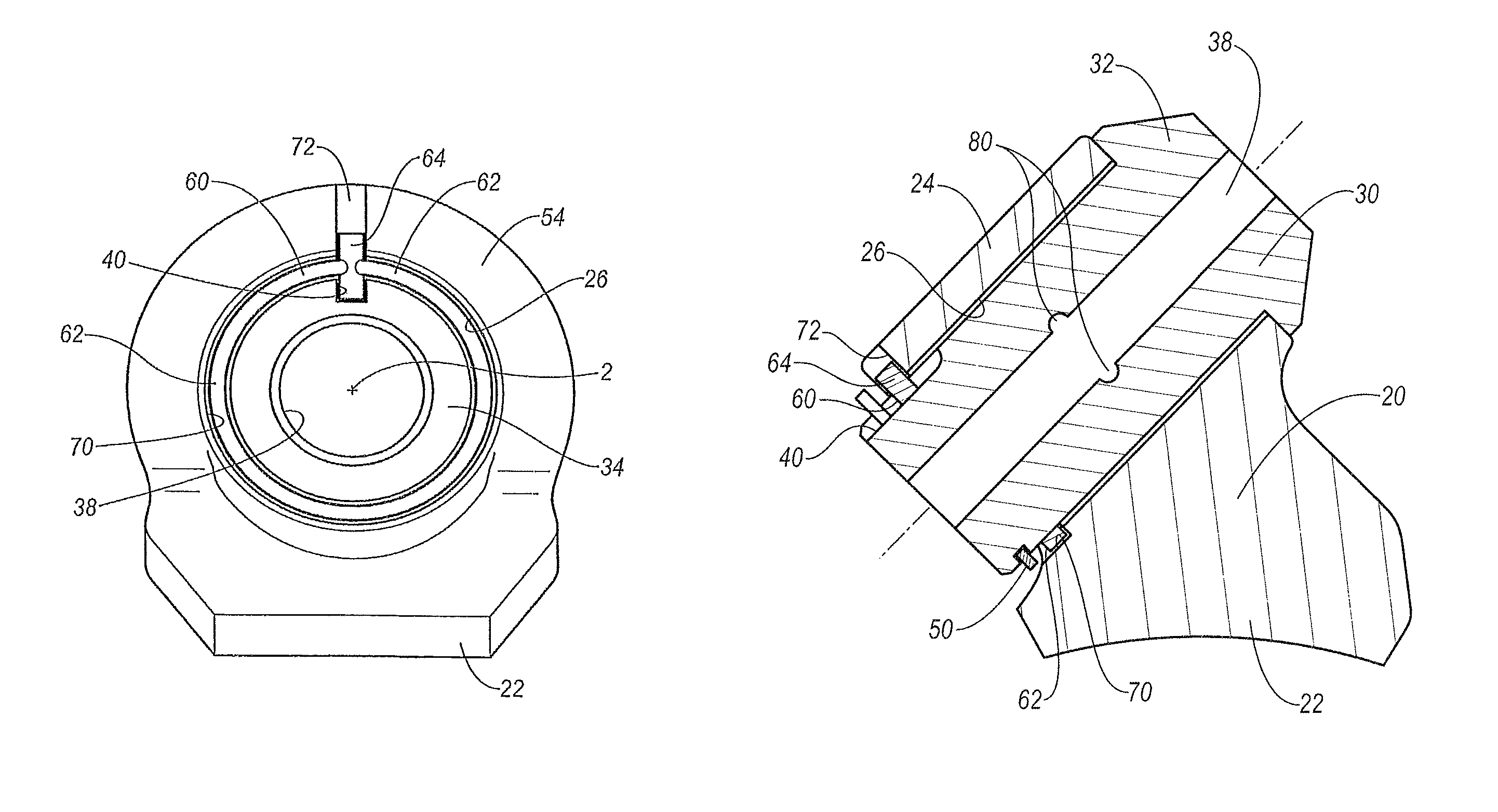
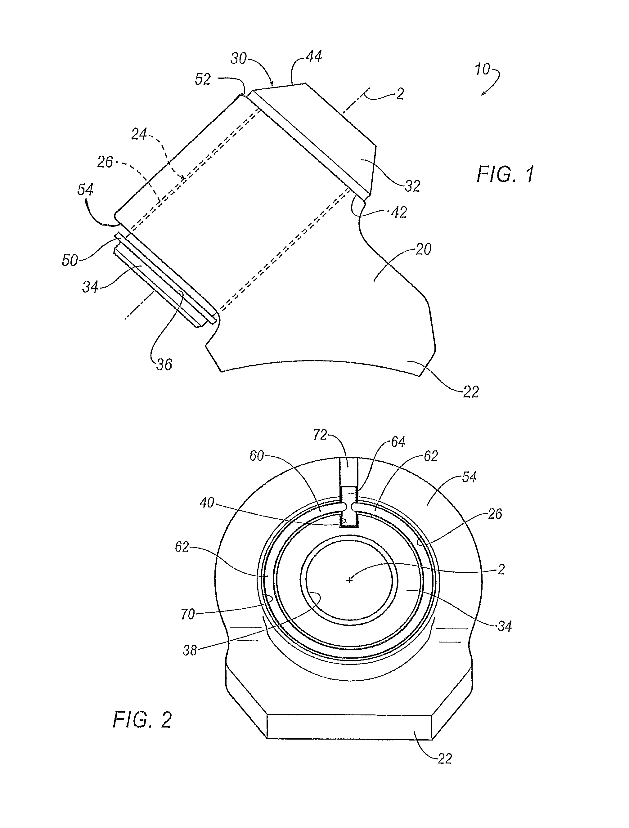
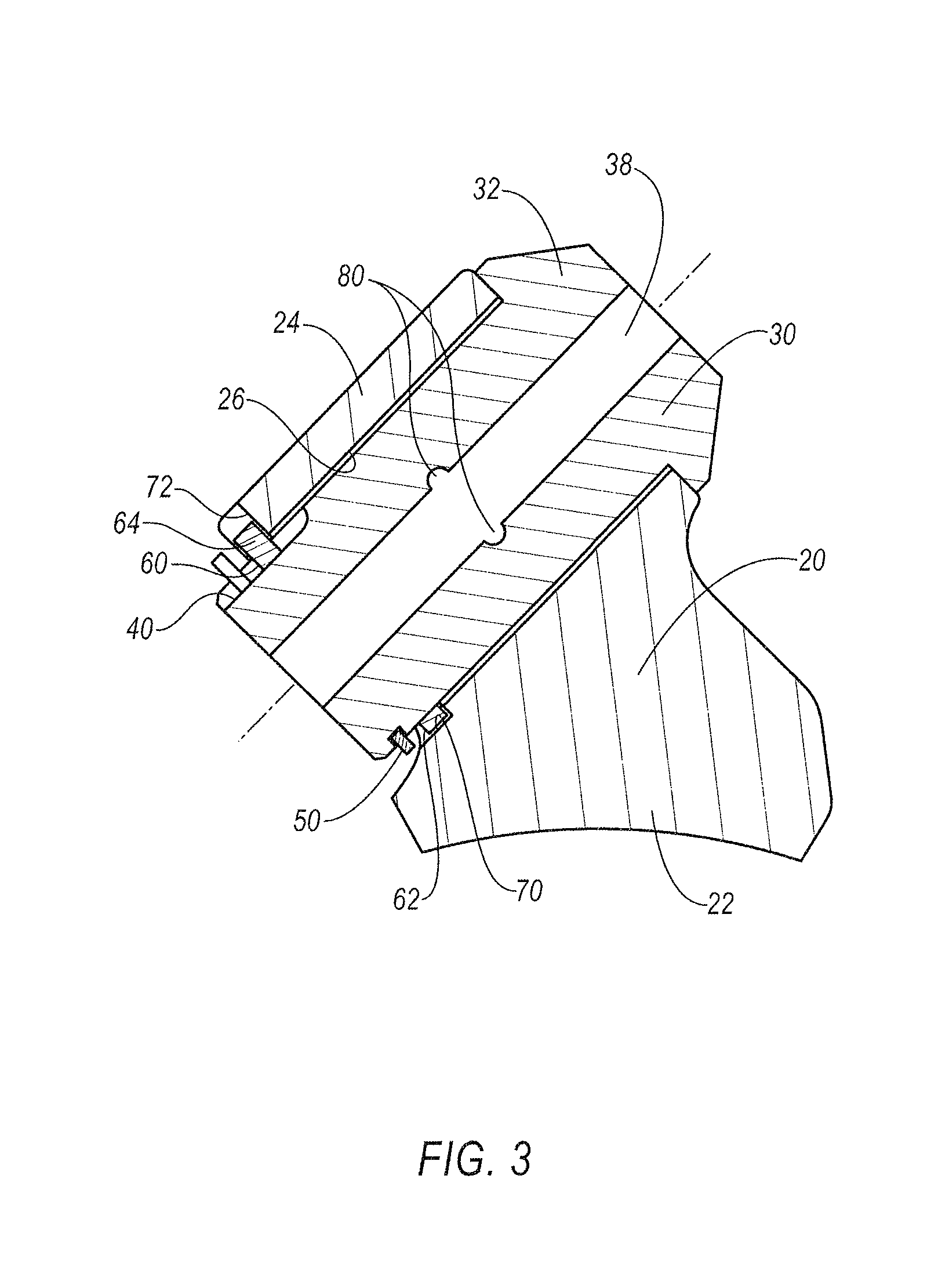
As used herein, the terms “channel”, “slot” and “notch” are similarly defined as an indentation in a surface and may include not only depressions in a surface but also slots defined by raised portions of the surface. The use of the terms “channel”, “slot” and “notch” within this specification is intended to instructive as to location of the element, e.g., at the wear sleeve or at the holder portion within an embodiment and is not intended to limit the terms beyond the definition giv...


PUM


Abstract

A block and non-rotating wear sleeve for holding a cutting tool used with mining and construction is disclosed. A key is used to intersect with notches in the wear sleeve and block at a rear face of the wear sleeve and block to prevent rotational movement between the wear sleeve and block. Locating the key and notches at the rear face provides an easily manufactured anti-rotation means which is also sheltered from the most of the abrasion experienced by the block and wear sleeve.

Description

FIELD OF THE INVENTIONThe present invention relates to tools and tool assemblies for mining and construction, more particularly, is concerned with retention of wear sleeves within a bit holder of the tool assembly.BACKGROUND INFORMATIONRotatable cutting tools are used in conjunction with a machine used to break up (or cut) a substrate such as coal, rock, asphalt pavement, asphaltic concrete, concrete or the like. In its very basic aspects, such a machine includes a driven member (e.g., a chain, a wheel or a drum), a holder either directly or indirectly mounted to the driven member, and a rotatable cutting tool rotatably held in the holder. It is the cutting tool that impinges the earth strata so as to break it into pieces and chunks upon impact.Rotatable cutting tools and the holders operate in a high wear environment. These components inevitably fail due to the severity of the operating conditions; e.g. gritty, dusty and highly abrasive. While it is expected that the cutting tools ...

Claims


Application Information

Patent Timeline
Patent Type & Authority Patents(United States)
IPC IPC(8): E21C35/197E21C35/19
CPCE21C35/18E21C35/197
Inventor KELLER, DONALD E.ROWLETT, DON C.
Owner KENNAMETAL INC
Why Eureka
Try Eureka