Eureka AIR delivers breakthrough ideas for toughest innovation challenges, trusted by R&D personnel around the world.

Flanged tube apparatus

Active Publication Date: 2015-06-25
SAINT GOBAIN PERFORMANCE PLASTICS CORP
View PDF4 Cites 13 Cited by
  • Summary
  • Abstract
  • Description
  • Claims
  • Application Information

AI Technical Summary

Benefits of technology

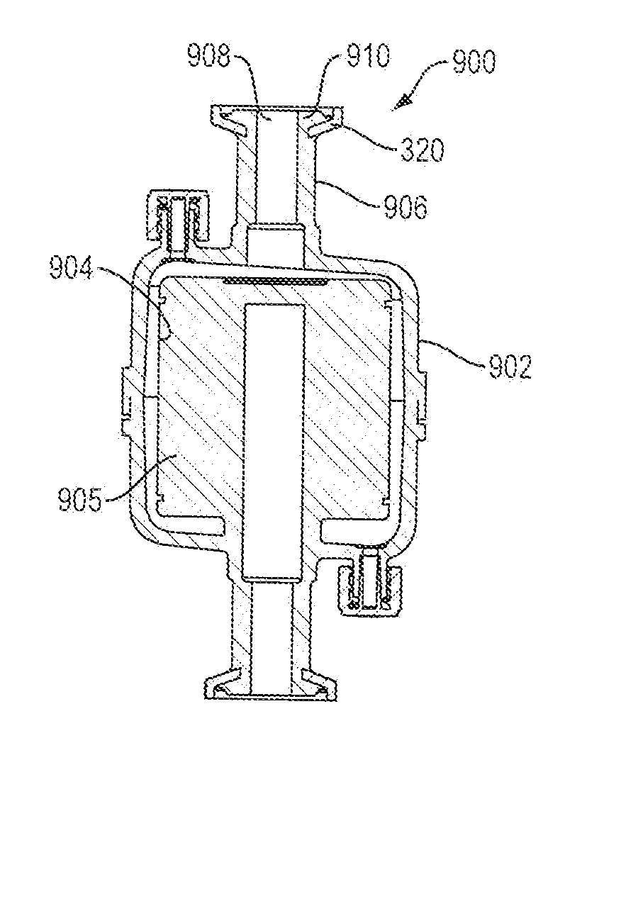
The patent is about an insert used in a tube / flange assembly. The insert has surface structures, like ridges or channels, that help keep it secure in position during high-heat and pressure sterilization procedures. These surface structures create a mechanical lock and prevent rotational movement of the insert. This makes it easier to maintain the assembly's integrity during sterilization.

Problems solved by technology

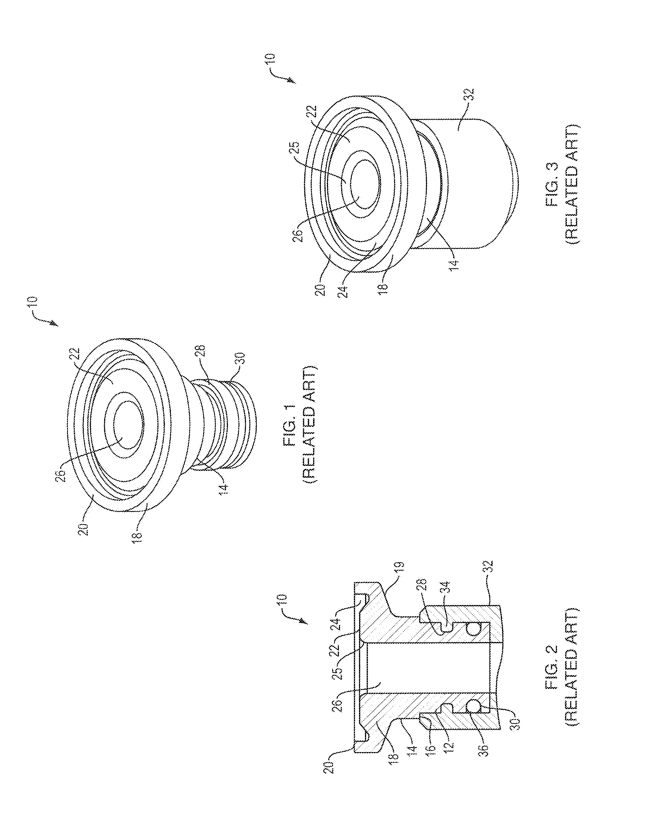
There are, however, drawbacks to use of polymeric materials when the application to which the tri-clamp construction is used requires regular and periodic sterilization procedures such as those used in the pharmaceutical industry.
Chief among the drawbacks is the propensity of some of the polymer-based flanges to deform during prolonged autoclaving and other high temperature sterilization techniques.
The deformation can lead to improper sealing between mated flanges as well as a reduction in structural integrity after the sterilization procedure.
This configuration does address problems with flange deformation and seal failure, but presents an additional set of issues that make the solution less than desirable.
The first issue is the exposure of the metallic flange to the fluids and / or gases introduced into the tube / flange assembly when assembled to a second tube secured with the tri-clamp.
This potentially limits the selection of materials that could be used to construct the metallic flange.
As the flange material differs from the tube material, fluids and / or gases that may be compatible with the tube polymer material may not be suitable for exposure to the metallic material thereby limiting the range of fluids and / or gases that may be used in the apparatus having the tri-clamp.
A second problem is the need for tight dimensional tolerances between the tube and flange segment to achieve a commercially acceptable seal between the parts that must be maintained through cycles of use, cleaning and sterilization.
The relatively complicated construction also adds considerably to the cost of producing the flange.
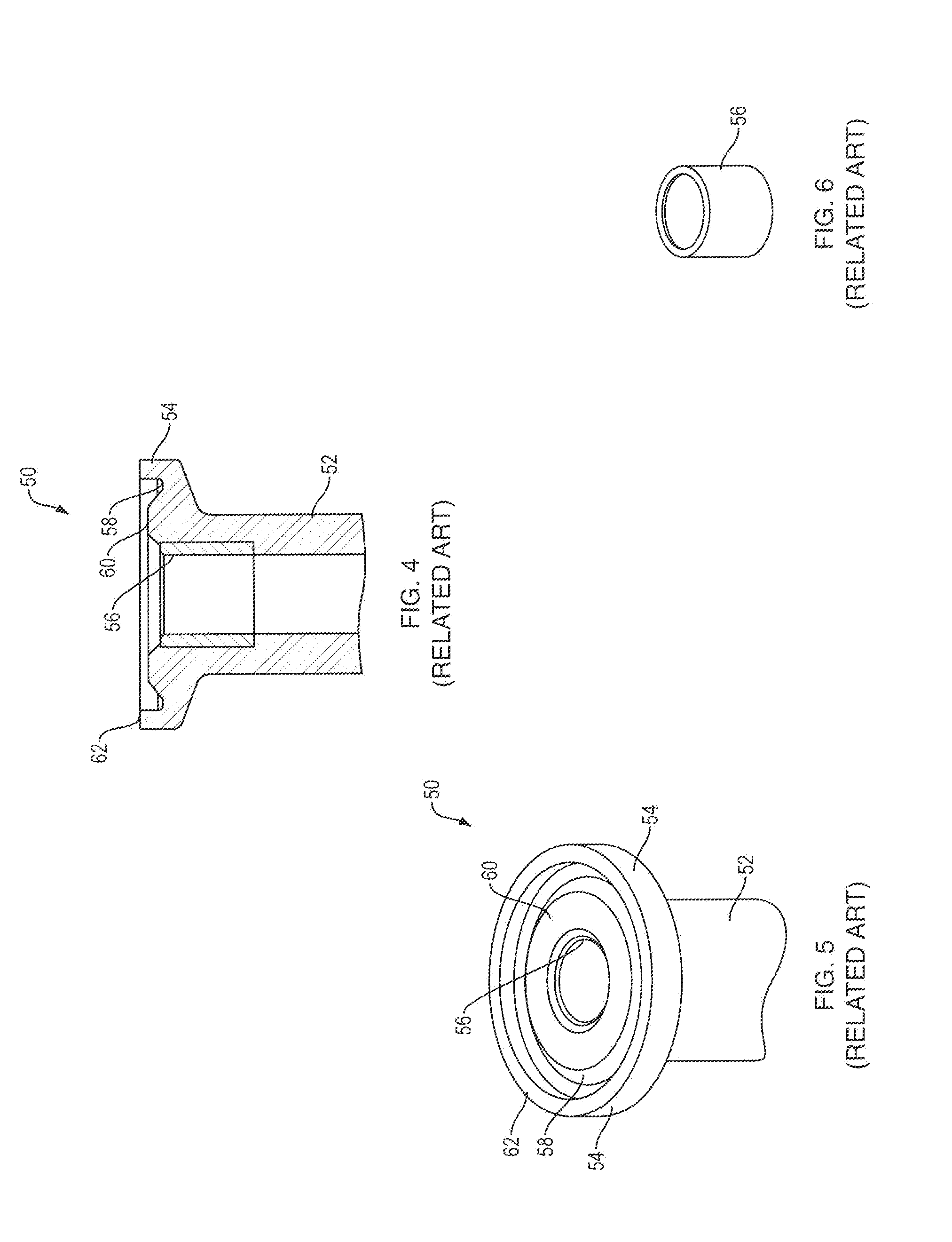
Although this configuration provides additional support for the flanged tube end, the material comprising the annular flange outside the diameter of the insert does not benefit from the insert's support.
The radially distant flange portions are subject to the same issues regarding flange deformation and potential leakage.

Method used


Image

  • Flanged tube apparatus
  • Flanged tube apparatus
  • Flanged tube apparatus

Examples


Embodiment Construction

[0099]Referring to FIGS. 7 and 8, in one aspect of the disclosure, a tri-clamp assembly shown designated generally as 100 includes a pair of flanged tubes 110, a gasket 115 and a clamp structure 130. The tubes 110 each have a cylindrically-shaped tube body 112, a lumen 126 defined by body 112 and a radially extending annular flange 118 formed on each tube's end. A flange insert (not shown, but various embodiments of which are disclosed below), is secured in each flange 118. Each flange 118 has portions that define an annular channel for receiving tri-clamp gasket 115.

[0100]Gasket 115 is a substantially circular disc with a raised perimeter shoulder that extends axially from the plane of the gasket body in both axial directions. The axially extended shoulders 119 are configured and dimensioned to fit within the channels formed in flanges 118. An inner portion of the gasket body defines a centrally located gasket bore 117 that permits gases and / or fluids to flow substantially unimpede...


PUM

PropertyMeasurementUnit
Diameteraaaaaaaaaa
Shapeaaaaaaaaaa
Distanceaaaaaaaaaa

Abstract

An improved flanged tube assembly with insert-reinforced tube flanges to prevent tube flange deformation and leakage when subjected to high compressive forces as well as sustained high-temperature procedures. The flange inserts are configured to form the flange portion of a flanged tube, or configured to provide structural support to the portions of the flange integral to the associated tube. The inserts may be metallic or polymer based and formed with various structural features to create a mechanical lock between the insert and the material used to make the tube / flange assembly. The inserts can be incorporated into the tube flanges so as to provide the desired support without being exposed to any fluids and / or gases that may flow through the reinforced tube / flange assemblies.

Description

FIELD OF THE DISCLOSURE[0001]The disclosure relates to improvements to clamped assemblies having flanged tubes in filtration and piping systems. More particularly, the disclosure concerns flange reinforcements for flanged tubes, pipes, filter housing ports and standalone tube fittings used in tri-clamp assemblies and the like to improve durability and adaptability to high temperature environments such as those experienced in temperature-based sterilization procedures and to simplify flange reinforcement design.BACKGROUND OF THE DISCLOSURE[0002]Flanged tubes, such as those used in tri-clamps, and similar to the novel one shown generally in FIG. 7, include four basic components (such as tri-clamp couplings constructed according to ISO 2852, DIN 32676, BS 4825). A pair of tubes 110 having flanged ends configured to register against one another and to enclose a sealing gasket 115 to create an airtight and fluid-tight seal. The flanges are maintained in registration with a clamp structur...

Claims


Application Information

Patent Timeline
IPC IPC(8): B01D35/30B01D63/00B01D29/01B01D15/10B01D46/54B01D53/04B01D63/14F16L23/06B01D46/52
CPCB01D35/30F16L23/06B01D63/00B01D29/016B01D46/521B01D2253/206B01D53/0415B01D63/14B01D15/10B01D2253/102B01D46/543B01D65/00B01D2313/02B01D2313/13B01D2313/20F16L23/032B01D2201/342B01D46/10F16L23/10F16L47/14F16L23/04B01D46/0002B01D46/0012B01D2265/02B01D2313/205
Inventor LIN, ZHENWU
Owner SAINT GOBAIN PERFORMANCE PLASTICS CORP
Why Eureka
Eureka Blog
Learn More