Door lock with adjustable mounting posts

a technology of mounting posts and door locks, applied in the field of door locks, can solve the problems of poor coupling between the door lock and the door, difficulty in drilling operation, time-consuming, etc., and achieve the effect of preventing rotational movement and preventing the disengagement of each mounting pos

Active Publication Date: 2009-08-11
I TEK METAL MFG
View PDF15 Cites 15 Cited by
  • Summary
  • Abstract
  • Description
  • Claims
  • Application Information

AI Technical Summary

Benefits of technology

[0005]In the most preferred form, each slot of the outer mounting plate has a length in the radial direction greater than a diameter of each through-hole of the door. Also, each hole of the inner mounting plate has a length in the radial direction greater than a diameter of each through-hole of the door. Each slot of the outer mounting plate has an inner end, an outer end more distant to the outer coupling seat than the inner end in the radial direction, and two parallel, rectilinear sides extending between the inner and outer ends. The coupling section of each mounting post includes two lateral sides slideably abutting the sides of one of the slots, allowing movement of each mounting post in the radial direction relative to the outer mounting plate and preventing rotational movement of each mounting post relative to the outer mounting plate. The outer end of each mounting post includes an outer flange having a diameter greater than a width of each slot perpendicular to the radial direction. A resilient washer is mounted between and frictionally abuts with the outer flange of each mounting post and an outer side of the outer mounting plate, preventing each mounting post from undesirably moving in the radial direction but allowing forcible movement of each mounting post in the radial direction. The coupling section of each mounting post further includes an inner flange having a diameter greater than the width of each slot. The inner and outer flanges of each mounting post are located on opposite sides of the outer mounting plate to prevent disengagement of each mounting post.

Problems solved by technology

The drilling operation is difficult and time-consuming due to precision requirements and due to overlapping of the new through-holes with the old ones.
Enlargement of the new through-holes by a file or the like is often required due to imprecise location of the new through-holes, leading to the risk of poor coupling of the door lock with the door.

Method used


Image

  • Door lock with adjustable mounting posts
  • Door lock with adjustable mounting posts
  • Door lock with adjustable mounting posts

Examples


Embodiment Construction

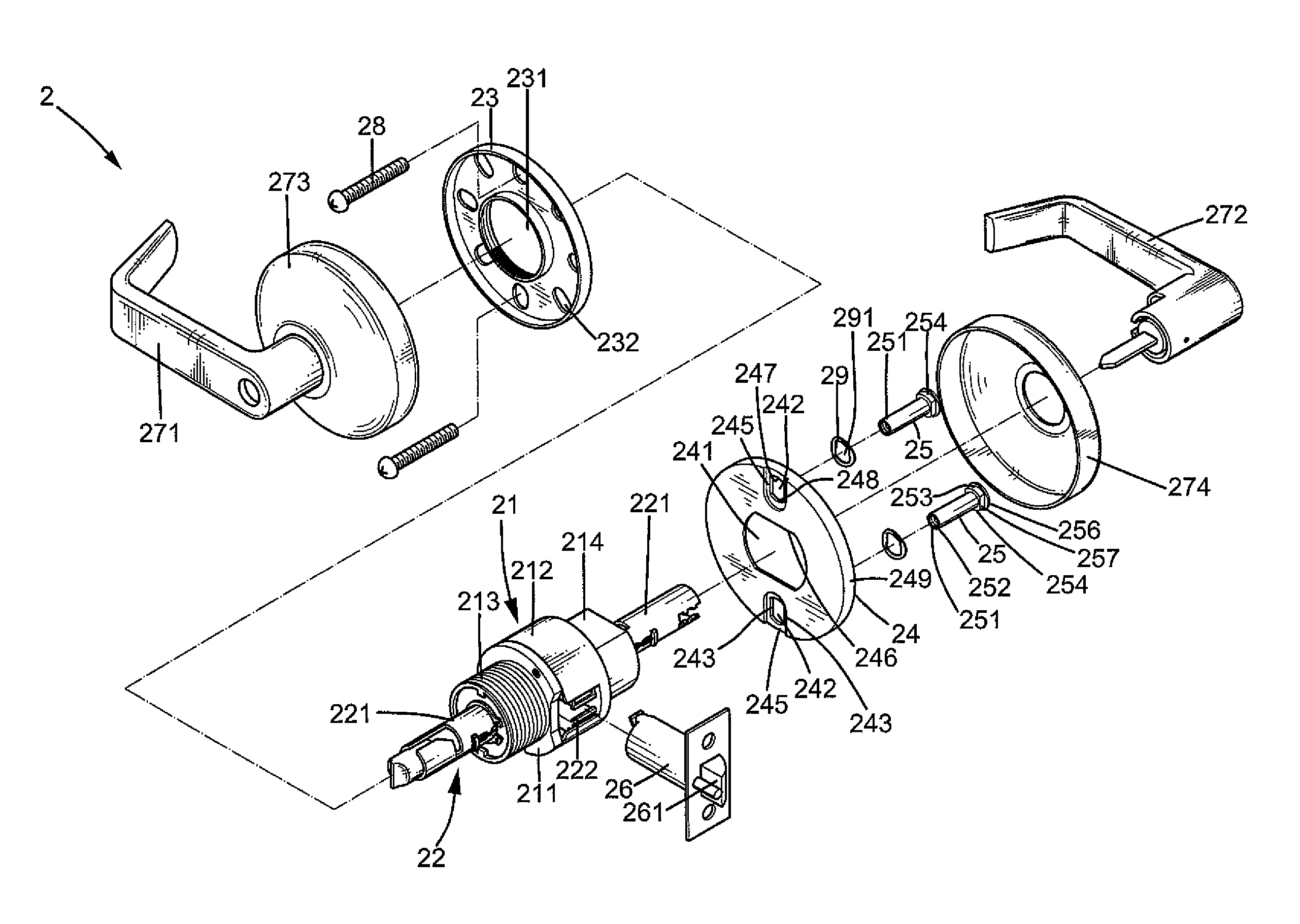
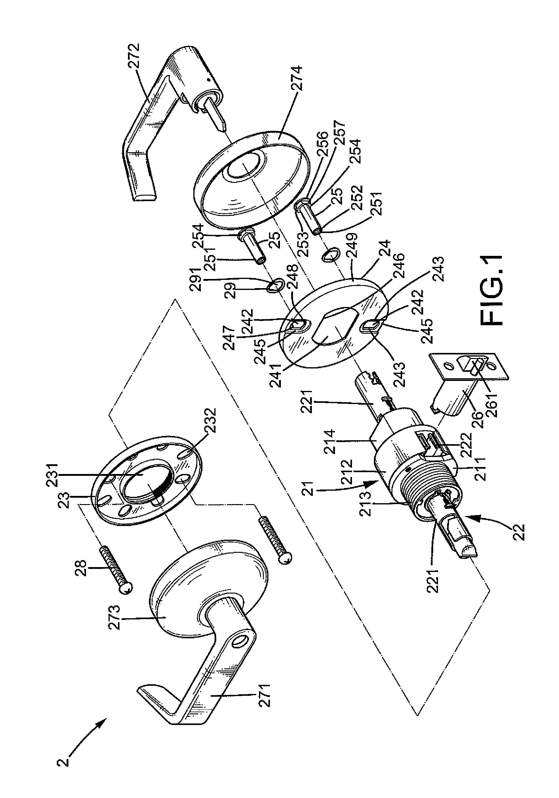
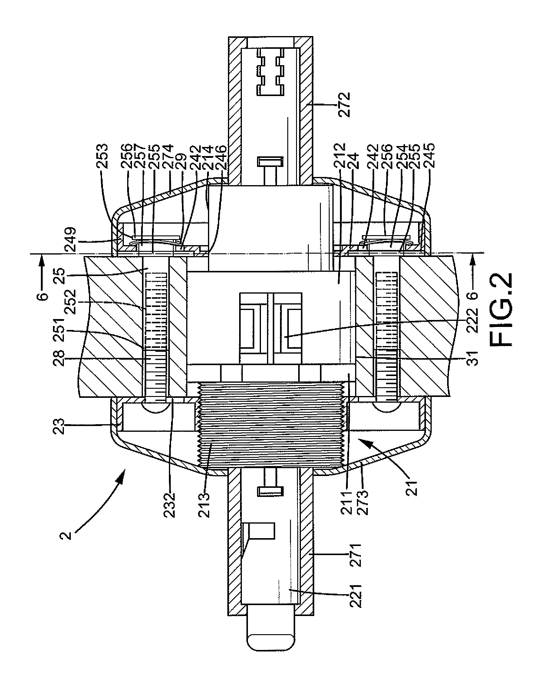
[0017]A door lock according to the preferred teachings of the present invention is shown in the drawings and generally designated 2. In the preferred form shown, the door lock 2 includes a casing 21 mounted in a bore 31 extending from an inner side through an outer side of a door 3. The casing 21 includes an inner coupling seat 211 and an outer coupling seat 212 coupled with the inner coupling seat 211. In the most preferred form shown, the inner coupling seat 211 includes outer threading 213, and the outer coupling seat 212 includes two diametrically opposed flat faces 214. A transmission mechanism 22 is received in the casing 21 and includes a spindle 221 and a retractor 222 operably connected to the spindle 221. Inner and outer handles 271 and 272 are respectively mounted to inner and outer ends of the spindle 221 for manual operation. The retractor 222 is connected to a latch 261 of a latch mechanism 26. When either handle 271, 272 is turned, the spindle 221 is rotated to move t...


PUM


Abstract

A door lock includes a casing mounted in a bare of a door. The casing includes inner and outer coupling seats to which inner and outer mounting plates are mounted respectively. The outer coupling plate includes two diametrically opposed slots located outside the bore of the door. The inner mounting plate includes a plurality of pairs of diametrically opposed holes. The inner mounting plate is rotatable relative to the inner coupling seat to a position in which one of the plurality of pairs of holes is aligned with the slots. Two mounting posts are extended through the slots and through two through-holes in the door. Each mounting post is slideably received in one of the slots, allowing the mounting posts to move toward or away from each other until a spacing between the mounting posts is equal to that between the two through-holes of the door.

Description

BACKGROUND OF THE INVENTION[0001]The present invention relates to a door lock and, more particularly, to a door lock with two adjustable mounting posts.[0002]A door lock of the type having two mounting posts generally includes a casing having an inner coupling seat and an outer coupling seat. An inner mounting plate is mounted on the inner coupling seat and includes two diametrically disposed mounting holes. An outer mounting plate is mounted on the outer coupling seat. Two mounting posts are secured to the outer mounting plate and extended through two through-holes in a door to which the door lock is mounted. Two screws are extended through the mounting holes in the inner mounting plate and into screw holes in the mounting posts to fix the inner and outer mounting plates to two sides of the door. The spacing between the axes of the mounting posts is either 65 mm or 70 mm. If the spacing between the centers of the through-holes in the door is not the same as that between the axes of...

Claims


Application Information

Patent Timeline
Patent Type & Authority Patents(United States)
IPC IPC(8): E05B1/00E05B15/02
CPCE05B9/08E05B63/0056Y10S292/60Y10T292/91Y10T292/82Y10T70/5832Y10T292/62
Inventor CHANG, HSUAN-CHENG
Owner I TEK METAL MFG
Why Eureka
Try Eureka