Ring structure of metal construction having a run-in lining

a metal construction and ring structure technology, applied in the field of aerodynamic properties, can solve the problems of increasing the complexity of the ring structure and thus the assembly as well as manufacturing outlay, increasing the flow loss, and reducing the mechanical stability of the structure, so as to reduce the flow loss, reduce the complexity of the ring structure and thus the assembly and manufacturing outlay, and reduce the effect of manufacturing cos

Inactive Publication Date: 2011-11-22
MTU AERO ENGINES GMBH
View PDF30 Cites 3 Cited by
  • Summary
  • Abstract
  • Description
  • Claims
  • Application Information

AI Technical Summary

Benefits of technology

[0006]Along the lines of the present invention, a ring structure of metal construction is provided, whose inner wall has a closed design and is made of a metal woven fabric and / or of a metal felt. The closed structure of the inner wall makes it possible to minimize flow losses. In addition, the ring structure according to the present invention is simpler in design than the segmented design known from the related art. By using a metal woven fabric and / or a metal felt for the closed inner wall, it is possible, on the one hand, to achieve substantial mechanical stability, and, on the other hand, circumferential strain does not lead to the formation of cracks in the inner wall. The metal woven fabric and / or the metal felt is capable, namely, of absorbing thermally produced strains without resulting in the formation of cracks.

Problems solved by technology

An inner wall segmented in this manner by expansion joints has the disadvantage that flow losses can occur.
In addition, the complexity of the ring structure and thus the assembly as well as manufacturing outlay are increased by an inner wall segmented in this manner.
Moreover, during operation, chipping off, washout or damage due to erosion can occur at the edges of the expansion joints, further increasing the flow losses.

Method used


Image

  • Ring structure of metal construction having a run-in lining
  • Ring structure of metal construction having a run-in lining

Examples


Embodiment Construction

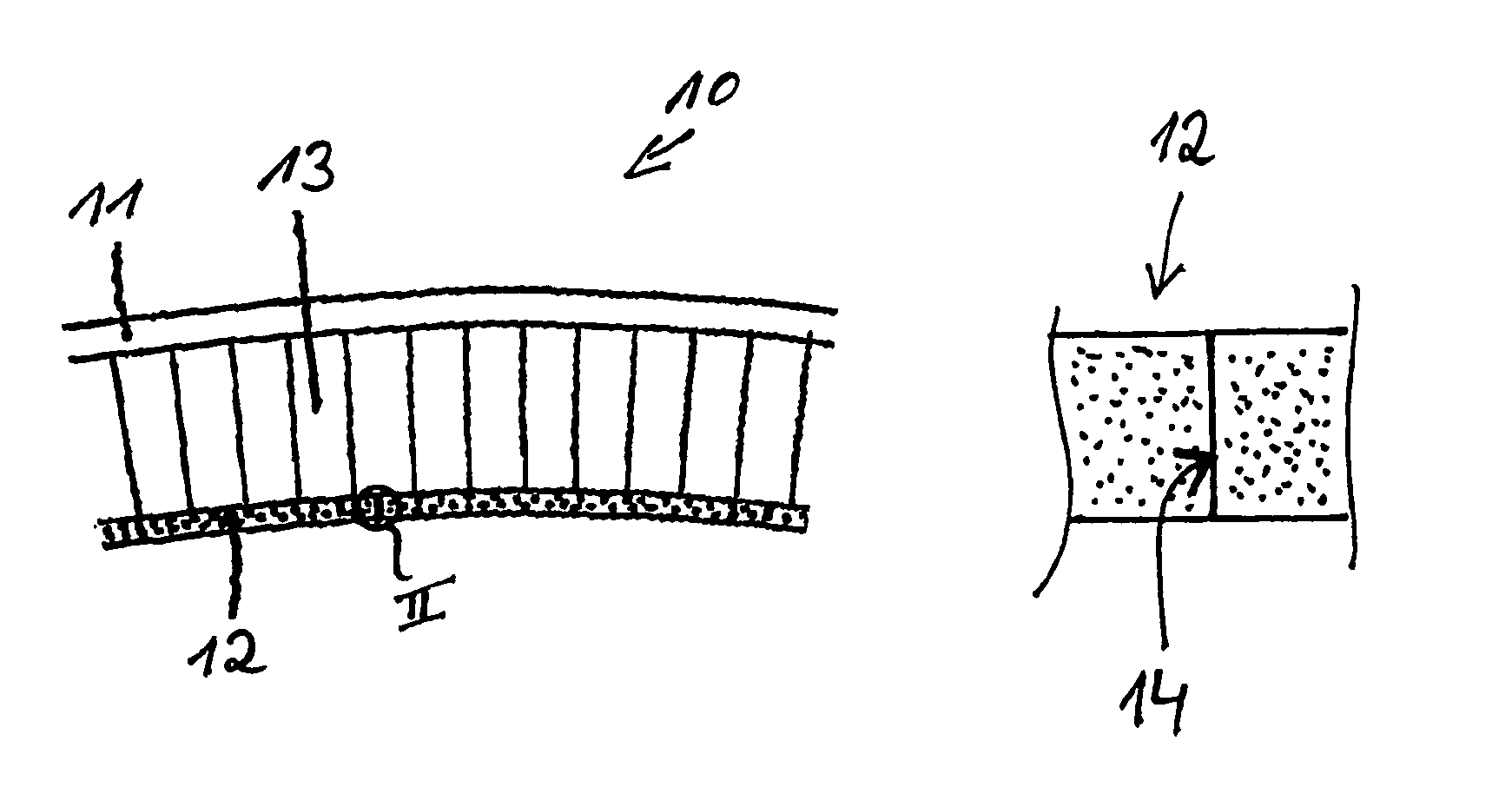
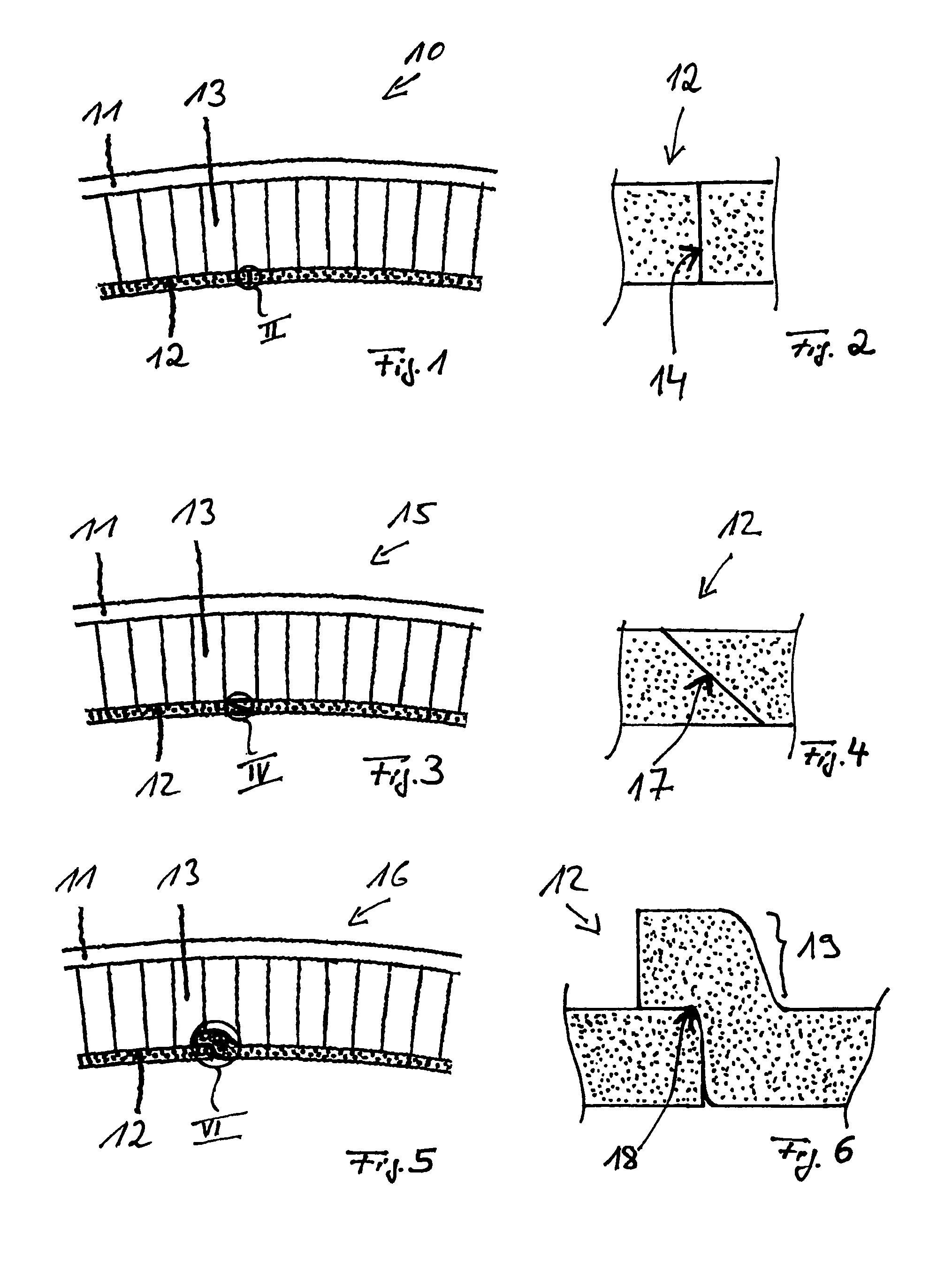
[0014]In the following, the present invention is described in greater detail with reference to FIG. 1 through 6.

[0015]FIGS. 1 and 2 show a first exemplary embodiment of a ring structure 10 according to the present invention, FIG. 2 illustrating detail II of FIG. 1 on an enlarged scale.

[0016]Ring structure 10 of the exemplary embodiment of FIGS. 1 and 2 includes a circular outer wall 11, a circular inner wall 12, as well as connecting structure 13 positioned in a sandwich-type arrangement between outer wall 11 and inner wall 12. Outer wall 11 is designed as a closed, mechanically stable housing wall of a compressor stage or turbine stage of a gas turbine, in particular of an aircraft engine. Connecting structure 13 positioned between outer wall 11 and inner wall 12 is designed as a hollow-chamber structure. In this context in cross section, hollow-chamber structure 13 may have hexagonal, rectangular or also round chambers, in one cross-sectional direction, disposed in parallel to the...


PUM


Abstract

A ring structure with a metal design for a moving blade of axially flowed through compressor and turbine stages, particularly in gas turbine engines is provided. The ring structure includes a circular ring-shaped outer wall, a circular ring-shaped inner wall, which is located at a short radial distance from the moving blade tips, and includes a joining structure provided in the form of hollow chamber structure between the outer wall and the inner wall. The outer wall is provided in the form of a closed, mechanically stable housing wall of the compressor or turbine stage, and the joining structure provided in the form of hollow chamber structure is joined in a fixed manner to the outer wall and to the inner wall, for example, by soldering, diffusion welding or other joining techniques. The inner wall is provided in the form of a closed, mechanically stable structure, which serves as a run-in lining for the moving blade tips and which is made of a metal woven fabric and/or of a metal felt.

Description

[0001]The present invention is directed to a ring structure of metal construction for a rotor blade region of axial flow compressor and turbine stages.BACKGROUND[0002]With regard to the aerodynamic properties of axial flow compressor and turbine stages, it is crucial that a small and as constant as possible radial gap be maintained between the blade tips and the outer flow channel wall. This requires most importantly that the wall structure exhibit sufficient dimensional stability and geometric precision. It is critical that the geometry be altered as little as possible by thermal and mechanical influences. The mostly hot working gas should essentially act only on the interior side of the structure; losses due to leakage through the structure must be minimized. In steady-state operation, it is advantageous when the mostly thermally induced dimensional variation of the wall structure is adapted temporally and in terms of magnitude to that of the bladed rotor. Since mechanical contact...

Claims


Application Information

Patent Timeline
Patent Type & Authority Patents(United States)
IPC IPC(8): F01D11/08F01D11/12
CPCF01D11/122F01D11/127F05D2230/238F05D2230/236F05D2230/237F05D2250/283F05D2300/601
Inventor DAEUBLER, MANFRED A.MUELLER-WITTEK, LEGAL REPRESENTATIVE, HORSTMENDRITZKI, LEGAL REPRESENTATIVE, RENATEHAIN, ULRIKEHUMHAUSER, WERNER
Owner MTU AERO ENGINES GMBH
Why Eureka
Try Eureka