Marker system with marker and installation apparatus

a marker system and installation apparatus technology, applied in the field of new marker system with a marker and an installation apparatus, can solve the problems of laborious marker installation, more resistance, difficult insertion action, etc., and achieve the effect of high efficiency and convenient way of marking

Active Publication Date: 2011-11-29
FLAGSHOOTER HLDG
View PDF37 Cites 6 Cited by
  • Summary
  • Abstract
  • Description
  • Claims
  • Application Information

AI Technical Summary

Problems solved by technology

However, the installation of the markers can be laborious, due to the numbers of markers that need to be placed as well as the manner in which the markers are inserted.
The markers may be inserted by hand into the ground with no mechanical assistance, but this requires repeatedly bending down to engage and insert the marker into the ground surface.
While these devices appear to work, some appear to actually make the insertion action more difficult by increasing the cross sectional profile of the portion of the marker that is being inserted into the ground (and thereby causing more resistance due to the larger profile), and / or requiring that a portion of apparatus be inserted in the ground as well.
This approach can make it difficult if not impossible to insert markers in ground that is highly compacted, stony, or is slightly frozen, to name a few of the factors making the insertion more difficult.
This approach tends to be less effective when, for example, using markers presenting a relatively large cross sectional profile and when the ground is compacted, stony, frozen, etc.
Some of the devices must be loaded with a marker each time that a marker is to be installed, which requires continual reloading of the device.

Method used


Image

  • Marker system with marker and installation apparatus
  • Marker system with marker and installation apparatus
  • Marker system with marker and installation apparatus

Examples


Embodiment Construction

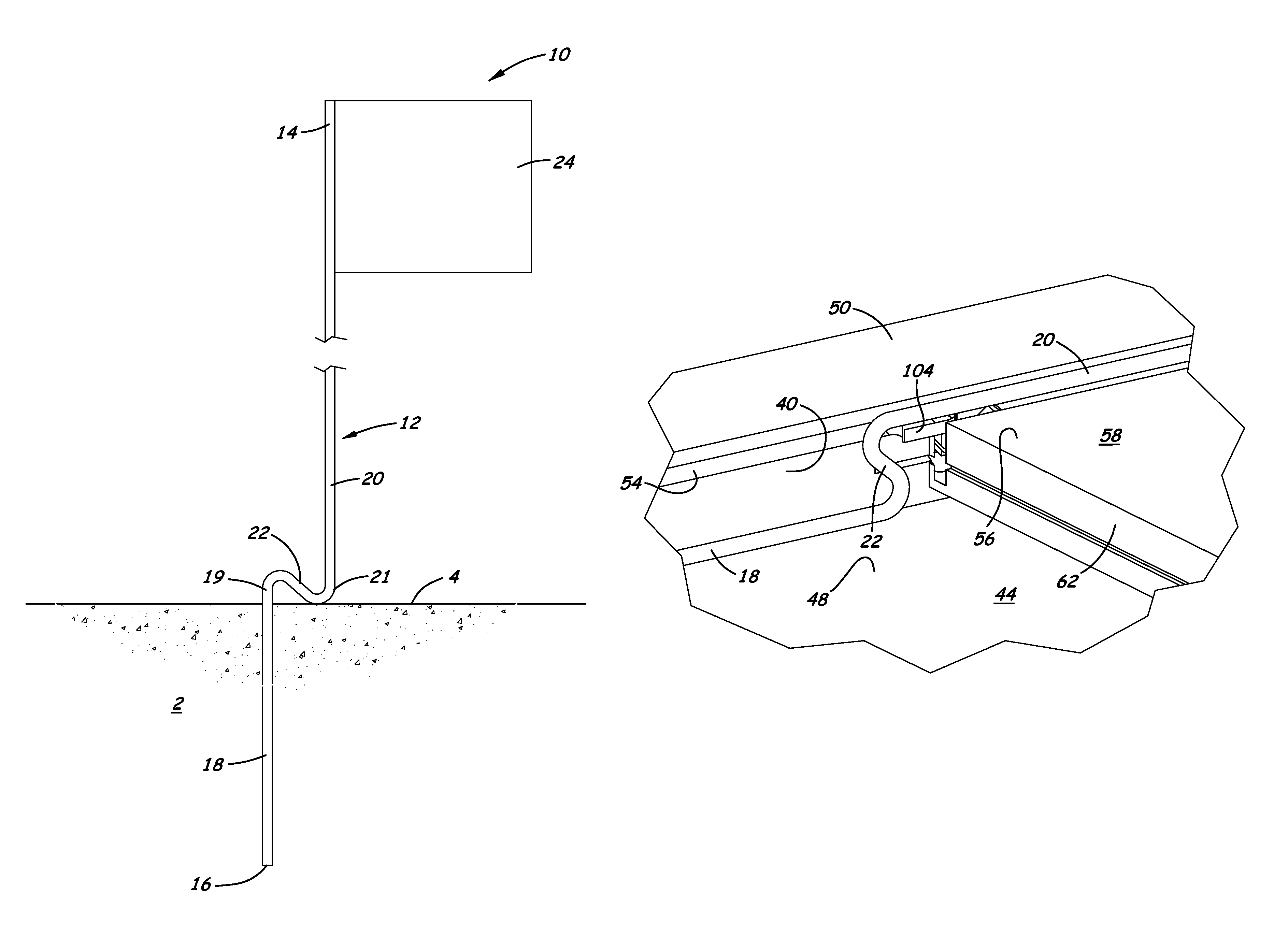
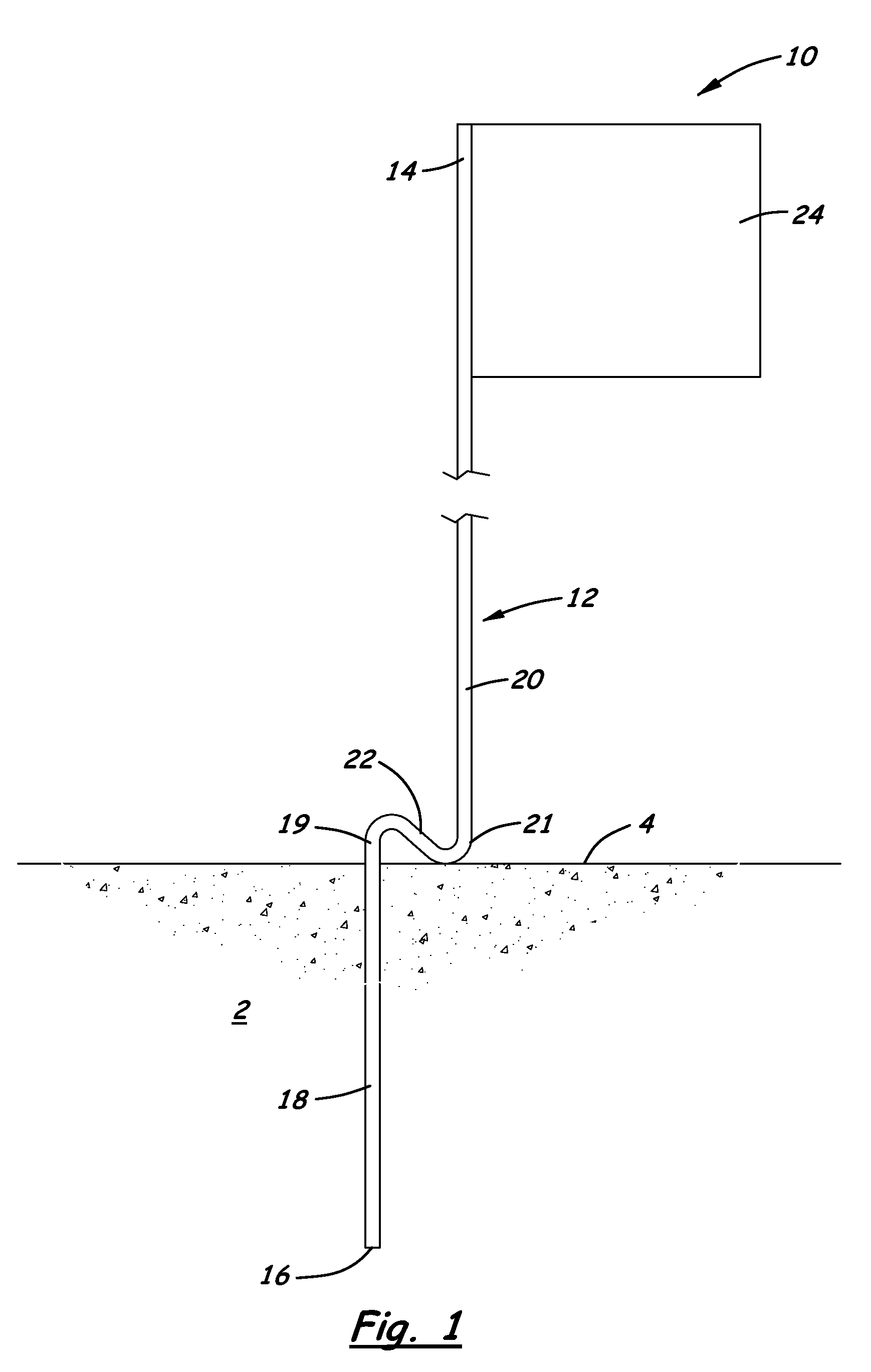
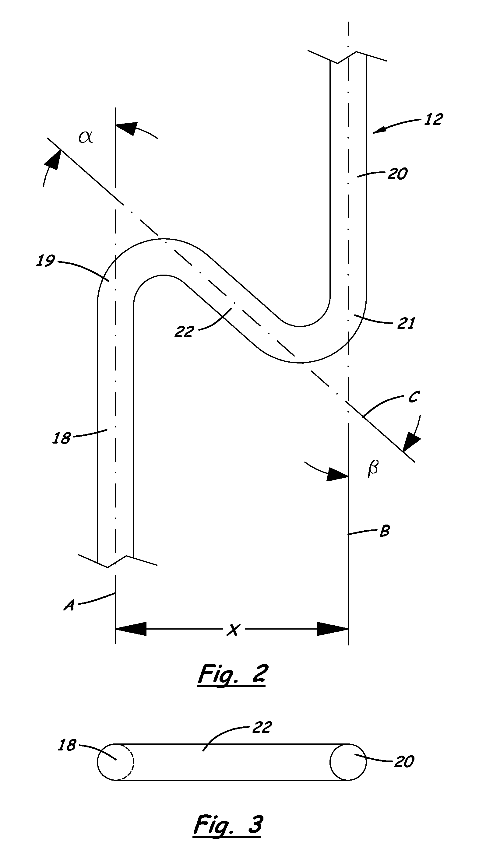
[0026]With reference now to the drawings, and in particular to FIGS. 1 through 11 thereof, the marker system with a marker and an installation apparatus of the present disclosure will be described.

[0027]In the following detailed description of embodiments according to the present disclosure, reference is made to the accompanying drawings which form a part hereof, and in which is shown by way of illustration specific preferred embodiments in which the system of the disclosure may be practiced. These embodiments are described in sufficient detail to enable those skilled in the art to practice the system of the disclosure, and it is to be understood that other embodiments may be utilized and that logical, mechanical and electrical changes may be made without departing from the spirit or scope of the disclosure. To avoid detail not necessary to enable those skilled in the art to practice the systems and methods of the disclosure, the description may omit certain information known to tho...


PUM


Abstract

A marker installation system comprises a marker comprising a shaft having a bottom end and a top end, and including an insertion portion, a mast portion, and an engagement portion located between the insertion portion and the mast portion. The engagement portion is configured to resist further insertion of the shaft into the ground beyond the insertion portion. The system includes a marker installation apparatus including a magazine assembly defining a magazine space in which the marker is positioned. The magazine space has a push position in the magazine space for receiving the marker. The apparatus includes a push assembly mounted on the magazine assembly to engage the engagement portion of the marker when the marker is located in the push position. The push assembly pushes the marker from the push position of the magazine assembly when the push assembly is actuated.

Description

BACKGROUND[0001]1. Field[0002]The present disclosure relates to ground marking systems, and more particularly pertains to a new marker system with a marker and an installation apparatus for marking a ground surface to, for example, indicate the presence of buried utilities, boundaries, events, advertising, etc. in a highly efficient and convenient manner.[0003]2. Description of the Prior Art[0004]It is often desirable to mark the ground surface to indicate, for example, the presence of underground utilities, the location of lot boundaries, and the like. This marking is often accomplished by the insertion of markers into the ground that extend upward from the ground surface and may include a flag at the top end. Numerous markers may be placed at spaced locations along the path of the buried utility line, and this may be true of each buried utility service (such as electric, gas, telephone, water, sewer).[0005]However, the installation of the markers can be laborious, due to the numbe...

Claims


Application Information

Patent Timeline
Patent Type & Authority Patents(United States)
IPC IPC(8): B25C5/10
CPCG01C15/04
Inventor CARRETTE, PAUL M.
Owner FLAGSHOOTER HLDG
Why Eureka
Try Eureka