Asymmetrical dental implant

a dental implant and asymmetrical technology, applied in dental implants, dental surgery, medical science, etc., can solve the problems of difficult alignment of the scalloped surface of the implant with the hard and soft tissue of the patien

Active Publication Date: 2011-11-29
WOHRLE PETER +1
View PDF8 Cites 14 Cited by
  • Summary
  • Abstract
  • Description
  • Claims
  • Application Information

AI Technical Summary

Problems solved by technology

In particular, in certain clinical setting, it may be difficult to align the scalloped surfaces of the implant with the hard and soft tissue of the patient.

Method used


Image

  • Asymmetrical dental implant
  • Asymmetrical dental implant
  • Asymmetrical dental implant

Examples


Embodiment Construction

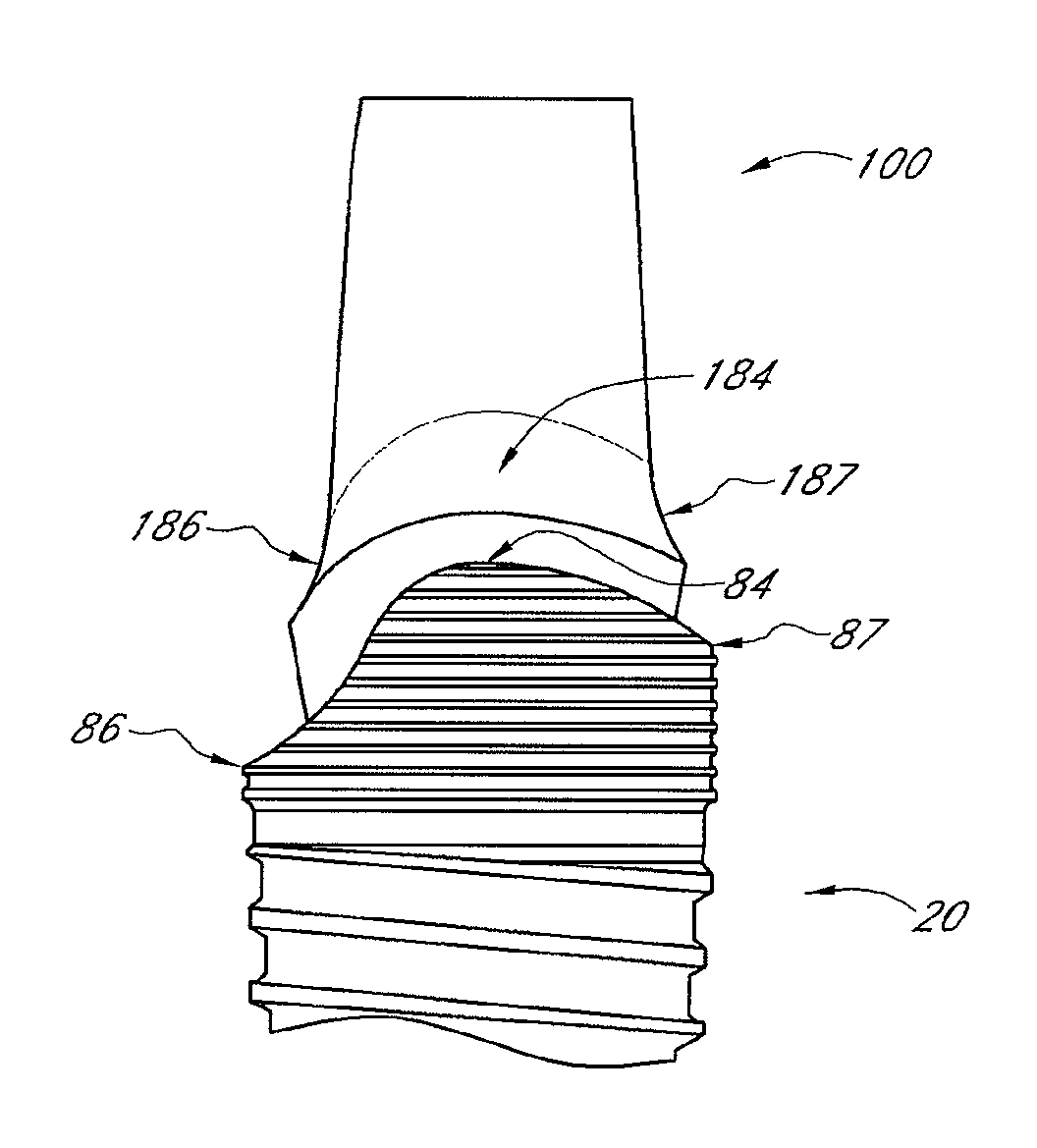
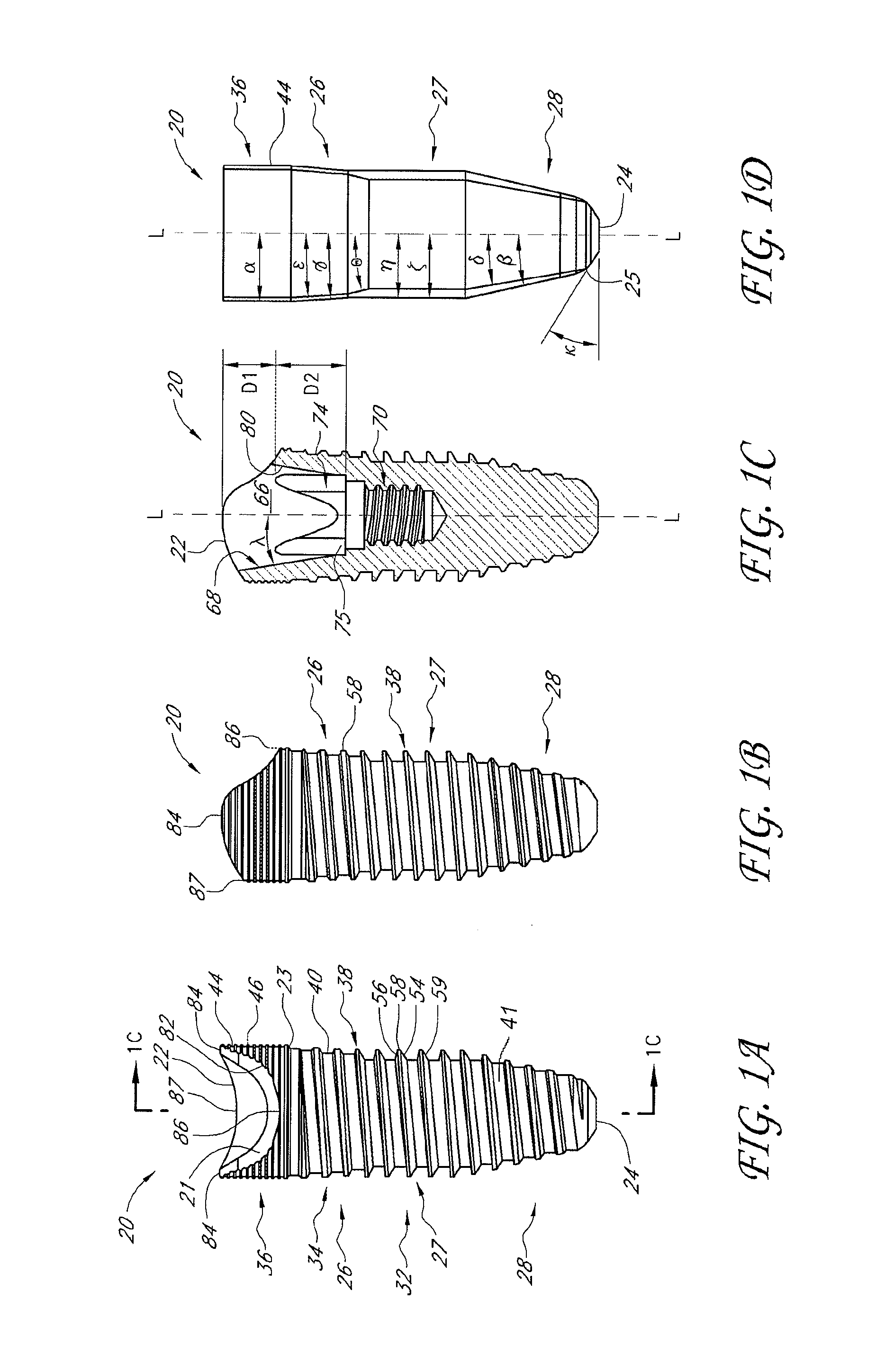
[0028]FIGS. 1A-1D illustrate an embodiment of a dental implant 20. In this embodiment, the implant 20 comprises an implant body 32, which includes a threaded portion 34 and a collar 36. The implant 20 may be made of titanium, although other materials may be used, such as various types of ceramics. The threaded portion 34 can include a thread 38 that is located on a root surface 40 of the threaded portion 34. As will be explained below, although the illustrated embodiment includes a single thread 38 with a single lead that extends helically around the implant, modified embodiments may include more threads (e.g., double or triple lead threads). In addition, as explained below, the root surface 40 and / or an outer surface formed by the face or tip of the thread 38 can taper inwardly with respect the apical direction and a longitudinal axis of the implant 20. However, in other embodiments, the root surface 40 and / or an outer surface formed by the face or tip of the thread 38 can be subst...


PUM


Abstract

A dental implant is provided for supporting a dental prosthesis. The implant can include a body having an outer surface, an apical end, and a coronal portion. The dental implant can include at least one thread located on at least a portion of the outer surface of the body. The dental implant can include a collar having a top surface that defines two peaks and two valleys, where the one valley is more coronal than the second valley.

Description

BACKGROUND[0001]1. Field of the Invention[0002]The present invention generally relates to dental restorations, and more specifically, to dental implants.[0003]2. Description of the Related Art[0004]Implant dentistry involves the restoration of one or more teeth in a patient's mouth using artificial components. Such artificial components typically include a dental implant and a prosthetic tooth and / or an abutment that is secured to the dental implant. Generally, the process for restoring a tooth is carried out in three stages.[0005]The dental implant is typically fabricated from pure titanium or a titanium alloy. The dental implant typically includes a body portion and a collar. The body portion is configured to extend into and osseointegrate with the alveolar bone. The top surface of the collar typically lies flush with the crest of the jawbone bone. The abutment (e.g., a final abutment) typically lies on the top surface and extends through the soft tissue, which lies above the alve...

Claims


Application Information

Patent Timeline
Patent Type & Authority Patents(United States)
IPC IPC(8): A61C8/00
CPCA61C8/0018A61C8/0077A61C8/005
Inventor WOHRLE, PETERTADROS, HATEM
Owner WOHRLE PETER
Why Eureka
Try Eureka