Quick release electronics platform

a technology for electronics platforms and trays, which is applied in the direction of washstands, suspension devices, furniture parts, etc., can solve the problems of limited ability of known mounting platforms to provide a full range of device mounting capabilities

Active Publication Date: 2011-12-13
CARNEVALI JEFFREY D
View PDF57 Cites 92 Cited by
  • Summary
  • Abstract
  • Description
  • Claims
  • Application Information

AI Technical Summary

Problems solved by technology

However, known mounting platforms apparatus are limited in their ability to provide a full range of device mounting capabilities.

Method used


Image

  • Quick release electronics platform
  • Quick release electronics platform
  • Quick release electronics platform

Examples


modular embodiment

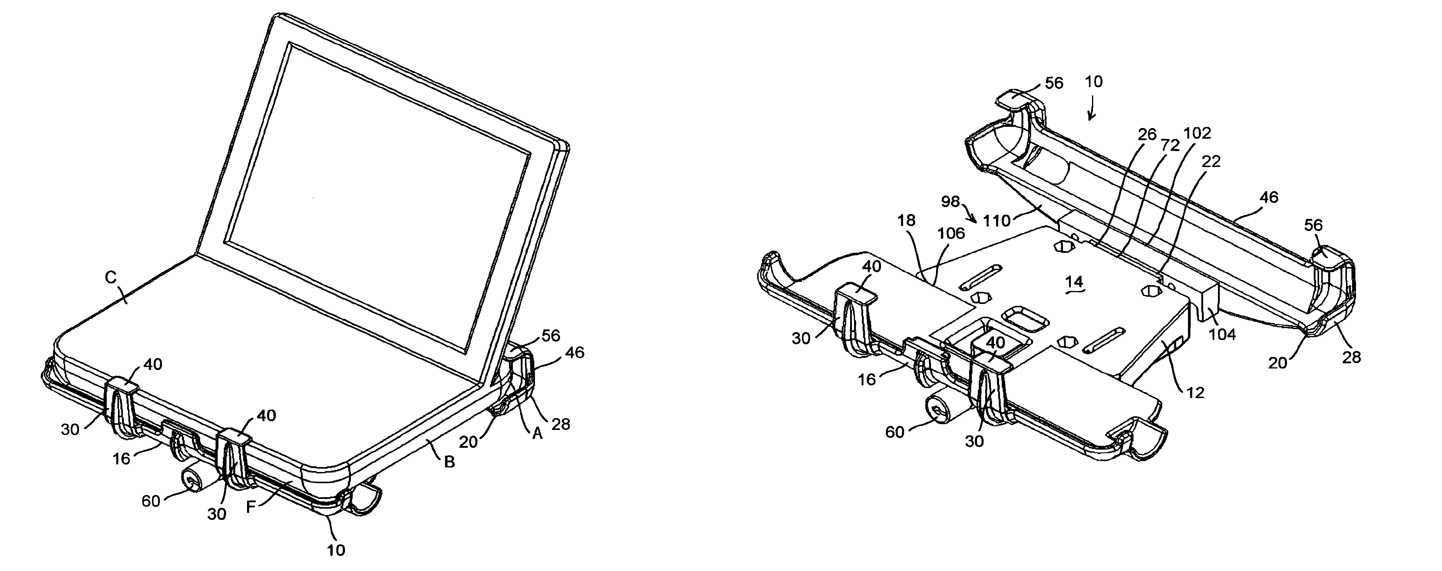
[0099]FIGS. 22 and 23 illustrate a modular embodiment of the novel device mounting platform apparatus 10 having a lap top computer or other similarly sized electronics device C secured therein. The body B of the mounted device C is seated on the generally upward facing, substantially planar device mounting surface 14 of the frame member 12, with a front portion F against the fence portion 30 of the jaw portion 16 and captured under the split lip portion 40. An aft portion A of the body B overhangs the rear edge 26 of the mounting surface 14 and is retained by the jaw portion 28 of the clamp member 20. When the clamp member 20 is in the retracted relationship relative to the frame member 12, as shown, the fence portion 46 of the jaw portion 28 compresses the front portion F of the body B against the fence portion 30 of the jaw portion 16, while the split lip portion 56 captures its aft portion A.

[0100]According to this modular embodiment of the novel device mounting platform apparatu...


PUM


Abstract

A device mounting platform apparatus having a reconfigurable biasing mechanism. The device mounting platform apparatus includes a frame member capable of being mounted in a vehicle and having a device mounting surface facing generally upward. A clamp member is slidably interconnected to the frame member along a first direction. A biasing mechanism is coupled between the frame and clamp members. The biasing mechanism is reconfigurable for urging a jaw portion of the clamp member along the first direction heading either toward or away from the frame member. The biasing mechanism is thus reconfigurable for either urging the clamp member open or urging it closed. A plurality of different jaw portions are interchangeably coupleable to the frame and clamp members in opposing relationship across the device mounting surface of the frame.

Description

[0001]This application is a Continuation-in-part and claims priority benefit of parent U.S. patent application Ser. No. 11 / 809,283 filed in the name of Jeffrey D. Carnevali on May 31, 2007 now U.S. Pat. No. 7,823,844, the complete disclosure of which is incorporated herein by reference.FIELD OF THE INVENTION[0002]The present invention relates generally to trays for holding portable devices, and in particular to quick release trays for holding portable electronic devices, including lap top computers and other similarly sized electronics devices such as notebooks, tablets, pen tablets, scanners, hand-held electronic devices, etc.BACKGROUND OF THE INVENTION[0003]Many after-market accessories being added in automobiles and other vehicles require specially designed mounting platforms that can accommodate the limited available space normally found in a vehicle for mounting add-on equipment, such as portable electronic devices, including by example and without limitation, laptop computers ...

Claims


Application Information

Patent Timeline
Patent Type & Authority Patents(United States)
IPC IPC(8): A47K1/08
CPCB60R11/02B60R11/0235B60R11/0252B60R11/0258B60R2011/0071B60R2011/0096
Inventor CARNEVALI, JEFFREY D.
Owner CARNEVALI JEFFREY D
Why Eureka
Try Eureka