Bottom system for geophysical survey (variants)

a geophysical survey and bottom system technology, applied in the field of geophysical surveys, can solve the problems of loss of the working capacity of the system, insufficient survey accuracy, and inability to complete and adequate, and achieve the effect of preventing the adhesion of the basic module's body

Active Publication Date: 2011-12-13
PXGEO UK LTD
View PDF7 Cites 12 Cited by
  • Summary
  • Abstract
  • Description
  • Claims
  • Application Information

AI Technical Summary

Benefits of technology

[0013]The present invention is dedicated to improvement of self-emerging bottom systems, allowing to carry out survey and measurements of different parameters of the seabed strata, that ensures increased prognosis accuracy. The invention enhances convenience and reliability of operation of the bottom systems; in particular, having smaller volumetric dimensions in the pre-start position, and allows optimizing the descending and lifting operations.
[0017]In one of the embodiments of the claimed bottom system, the basic module may be used independently (further called an ‘independent variant’). In this case, a rigid conical member is installed between the module and the load, which conical member is made of non-conducting material, for example, polyethylene, polyurethane, or similar materials. The conical member is used for fixation of the basic module's body in the horizontal plane and prevention of adhesion of the basic module's body to the ground.
[0018]In some embodiments, a magnetic measuring module may be additionally attached with a semi-rigid bar to the basic module, that allows reducing influence of the basic module's magnetic masses onto the results of magnetic field measuring, for example while measuring transient electromagnetic fields (further called a ‘bi-module variant’). Where the magnetic measuring module is joined to the basic module, the average distance from it to the magnetic sensors should be 0.5-0.8 meters. Influence of the magnetic masses decreases according to third power of the distance. For instance, the proposed system structure with a 5 meters bar ensures reduction of influence of the magnetic masses by 2.5-3 decades.

Problems solved by technology

The main disadvantage of such systems is impossibility of complete and adequate transmission of the changing ground parameters onto the signal measuring sensors, installed on the supporting tubular frame, equipped with metallic mechanisms for throwing away and pressing to the ground, that in combination with the presence of border ground-metal causes additional inaccuracies at the acoustic signals passage and finally results in insufficient accuracy of the survey.
Moreover (besides that), the use of the mechanisms for throwing away and pressing to the ground is not sufficiently effective (enough) because of their complexity, absence of control on their installation, that results in the placement of measuring sensors block in loose ground of the sea-bottom, and consequently leads to a loss in the working capacity of those system.
The buoy-based systems have a good transmission coefficient in the geophones channels due to great mass of the body; however the systems of this type have limitations on the setting depth, high risk of loss of the system, and require a sufficiently complex descending and lifting technology.
However, a high position of displacement sensors relatively to the sea-bottom and elastic fastening of the system to the load reduces sensitivity of the system to the displacement waves.
The disadvantage of such system is insufficient measuring accuracy, and a limited range of application.
Another disadvantage of all of the above mentioned bottom systems is that they allow measuring only a specific group of parameters, that is conditioned by differences in requirements for exploiting the bottom systems of different types.
The disadvantage of the system is that its deployment is limited to only measuring the magnetic field parameters.
Moreover, taking away the system off the board with the arms, directed upright down, increases a probability of damaging the electrodes and inductive sensors in case when during operation the water flow does not have enough time to move the arms into the vertical position, or bends one or several arms under the load, in particular, during operation on shallow water.

Method used


Image

  • Bottom system for geophysical survey (variants)
  • Bottom system for geophysical survey (variants)
  • Bottom system for geophysical survey (variants)

Examples


Embodiment Construction

[0024]While the invention may be susceptible to embodiment in different forms, there are shown in the drawings, and will be described in detail herein, specific embodiments of the present invention, with the understanding that the present disclosure is to be considered an exemplification of the principles of the invention, and is not intended to limit the invention to that as illustrated and described herein.

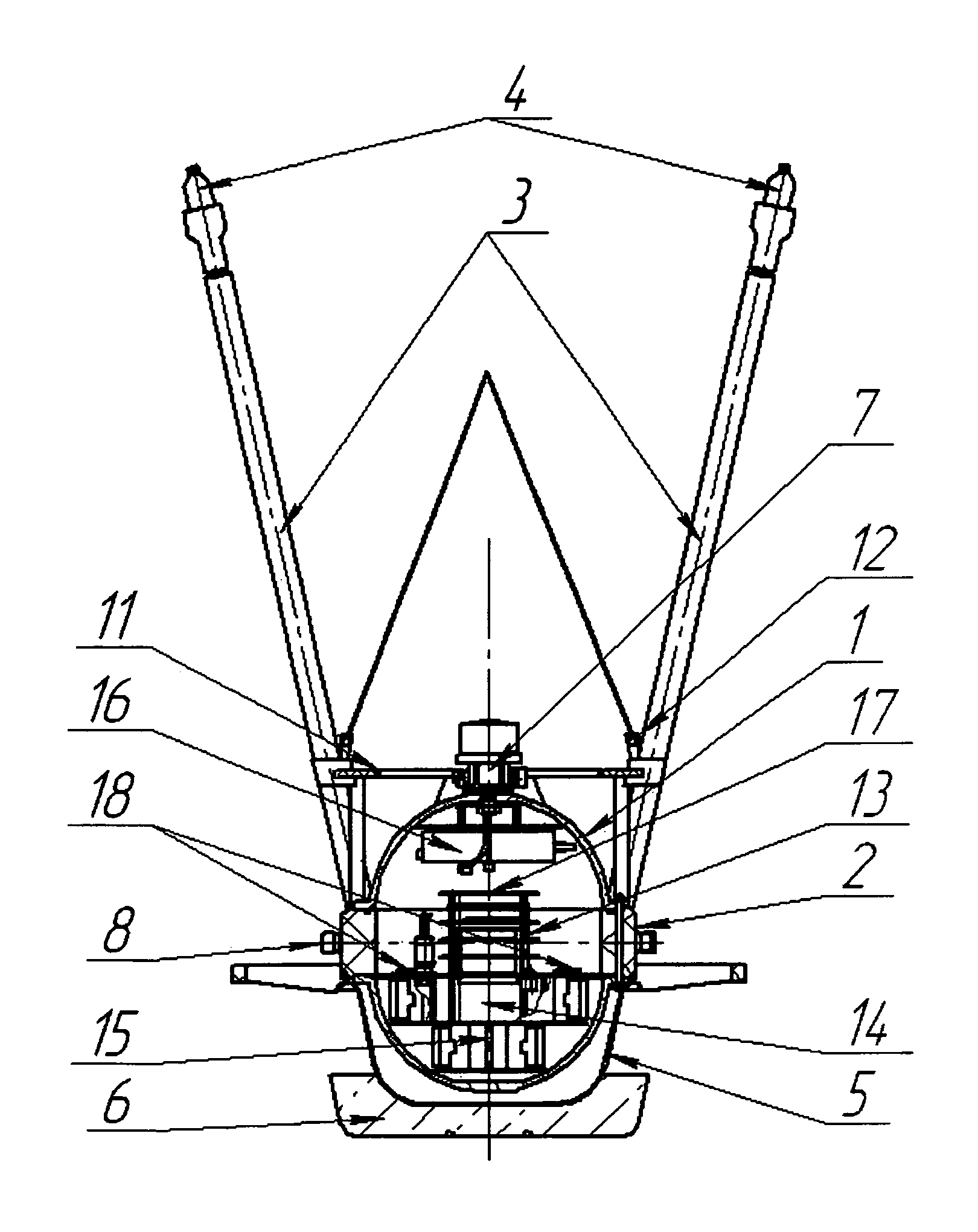
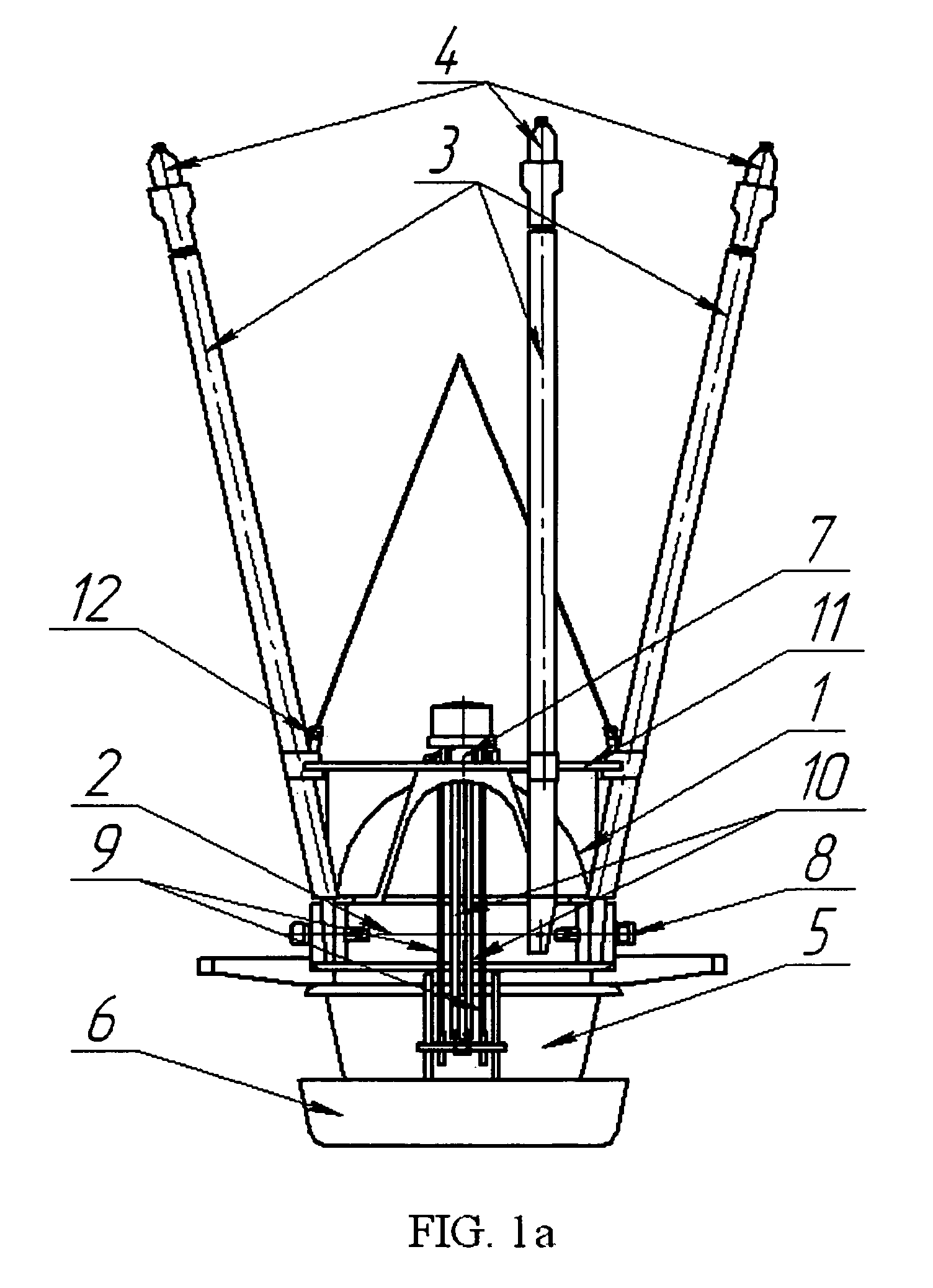
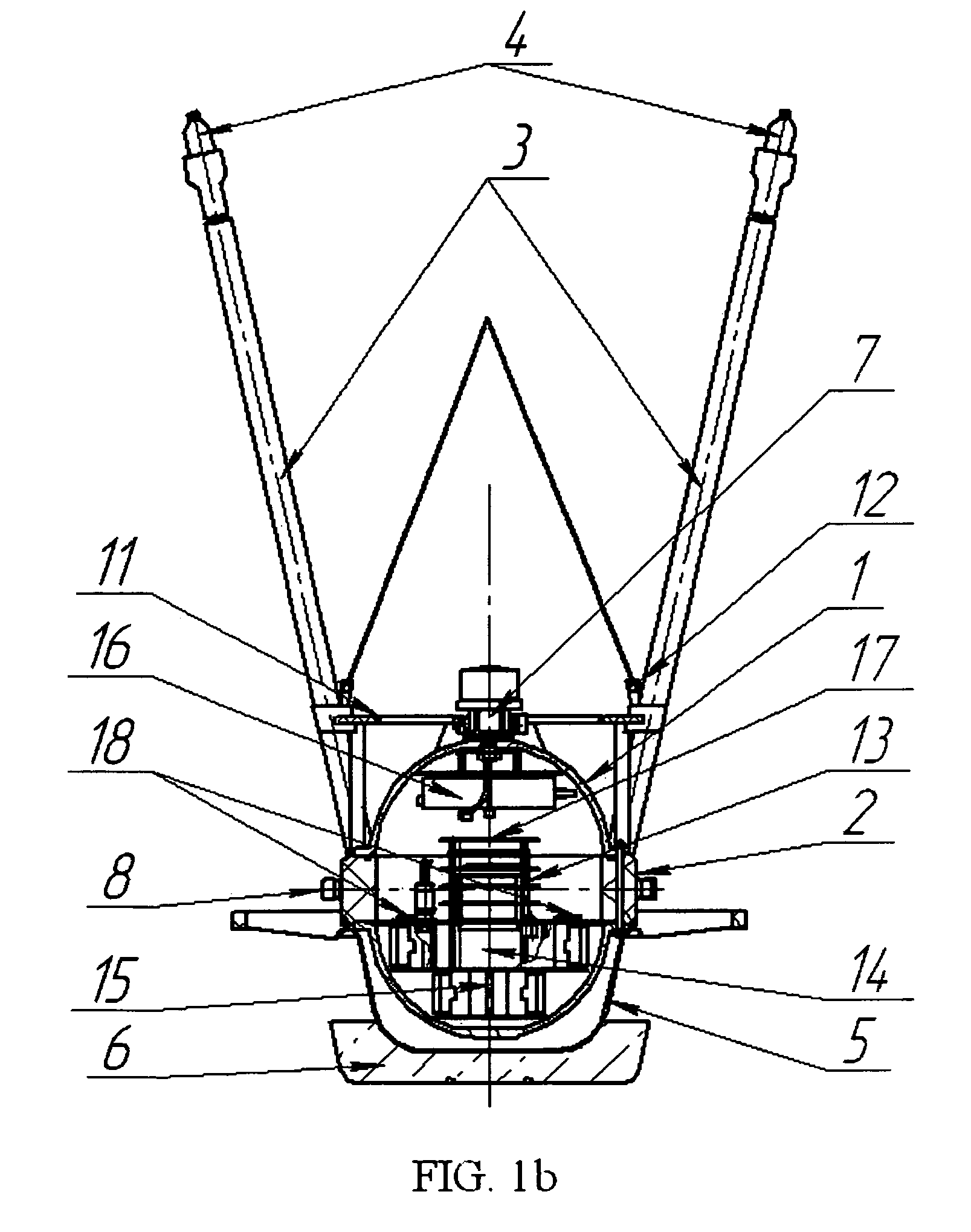
[0025]The following designations are used in FIGS. 1-4: 1—spherical hermetic body of a basic module, 2—insertion, 3—movable arms, 4—non-polarized measuring electrodes, 5—conical member (having a ‘pot’-like shape, similar to a truncated cone), 6—load preferably made of concrete, 7—acoustic release system preferably of an electrochemical type, 8—hermetic connectors, 9—Kevlar straps, 10—elastic tension bar, 11—rail, 12—arm fixing element, 13—registration device, 14—main power unit, 15—power unit of the release system, 16—electronic block of the release system, 17—angle sensor, 18—p...


PUM


Abstract

A bottom system related to equipment deployed for seabed geo-electrical survey is proposed, in preferred embodiments comprising a basic module, including registration and power supply means, or a combination of the basic module with at least one additional module: a magnetic characteristics measuring module or / and a seismic characteristics measuring module. The additional modules are connected with other modules through hermetic connectors. The modules are attached to a load with Kevlar straps, provided with an electrochemical release system. Arms with electrodes measuring electromagnetic characteristics of seabed, are attached to the basic module, in their initial position directed upwards at minimum 15° from the vertical, and fixed with fixing elements, connected with a releasing element of a device for descending and lifting the bottom station. The arms are made telescopic for convenient transportation. Independent embodiments without additional modules include a non-conductive conical member joined to the basic module and to the load.

Description

CROSS-REFERENCE TO RELATED APPLICATION[0001]This U.S. patent application claims priority under 35 U.S.C. 119 (a) through (d) from a Russian Federation patent application No. 2008107911 filed on 4 Mar. 2008. This application also contains newly disclosed parts.BACKGROUND OF THE INVENTION[0002]The invention relates to the field of geophysical survey, specifically to equipment deployed for marine geo-electrical survey, in particular, utilizing methods of induced polarization, magneto-telluric and / or seismic survey, and it is intended for prognosis of hydrocarbons deposits and deposits of other mineral products, as well as for exploration of the earth's crust structure.[0003]Currently, bottom systems with different structures and designations are widely known and used for marine geophysical survey and researches. Particularly, there are bottom seismic systems (RU 24890); Deep-water bottom self-emerging seismic system ADC-8 / Soloviev S. L., Kontar E. A., Dozorov T. A., Kovachev S. A. / / Izv...

Claims


Application Information

Patent Timeline
Patent Type & Authority Patents(United States)
IPC IPC(8): G01V3/00G01V3/08
CPCG01V3/15G01V3/40
Inventor TULUPOV, ANDREY VLADIMIROVICHLISITSIN, EVGENIY DMITRIEVICHPETROV, ALEXANDR ARKADYEVICHKYASPER, VLADIMIR EDUARDOVICH
Owner PXGEO UK LTD
Why Eureka
Try Eureka