Fluid pump with disposable component

a technology of disposable components and pumps, applied in the field of flushing pumps, can solve the problems of high manufacturing and maintenance costs, difficult for reusable pumps, and difficult for integral pumps,

Active Publication Date: 2012-01-03
CAREFUSION 303 INC
View PDF6 Cites 1 Cited by
  • Summary
  • Abstract
  • Description
  • Claims
  • Application Information

AI Technical Summary

Problems solved by technology

This is difficult for integral pumps where the pumping mechanism and fluid path are part of a single unit.
These reusable pumps, however, suffer from a number of drawbacks.
First, many designs are highly complex, resulting in high costs of manufacture and maintenance costs, and low reliability.
In addition, the pumps generally suffer from one or more design issues which result in less than optimum performance.
For example, it is desirable for the pump to include a flow sensor, and yet such a feature is often inconsistent with the design of the re-usable pump.
Also, these pumps generally have undesirable compliance.
Many commercial pumps suffer significantly due to undesirable compliance resulting in either significant change to average and instantaneous flow when varying intake and output pressures are experienced.
However, flow uniformity is degraded with increasing output pressure and pump segment compliance.
When the upper occluder opens, this excess volume moves back into the drip chamber, thus reducing net volume pumped and disturbing uniformity of flow.
A second drawback of dual chamber pumps is the likelihood of air being entrained within the pumping chambers.

Method used


Image

  • Fluid pump with disposable component
  • Fluid pump with disposable component
  • Fluid pump with disposable component

Examples


Embodiment Construction

[0028]In the following description, numerous specific details are set forth in order to provide a more thorough description of the present invention. It will be apparent, however, to one skilled in the art, that the present invention may be practiced without these specific details. In other instances, well-known features have not been described in detail so as not to obscure the invention.

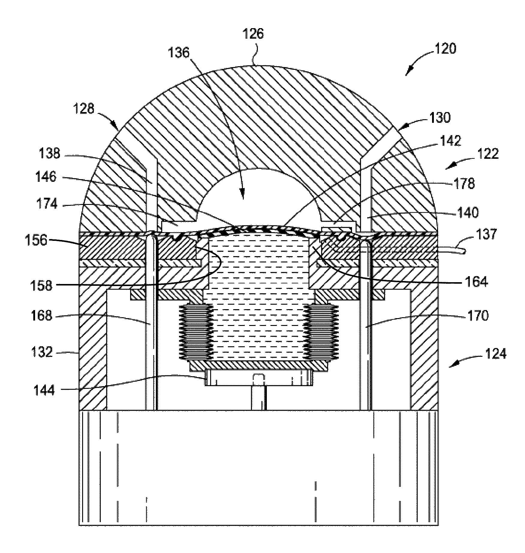
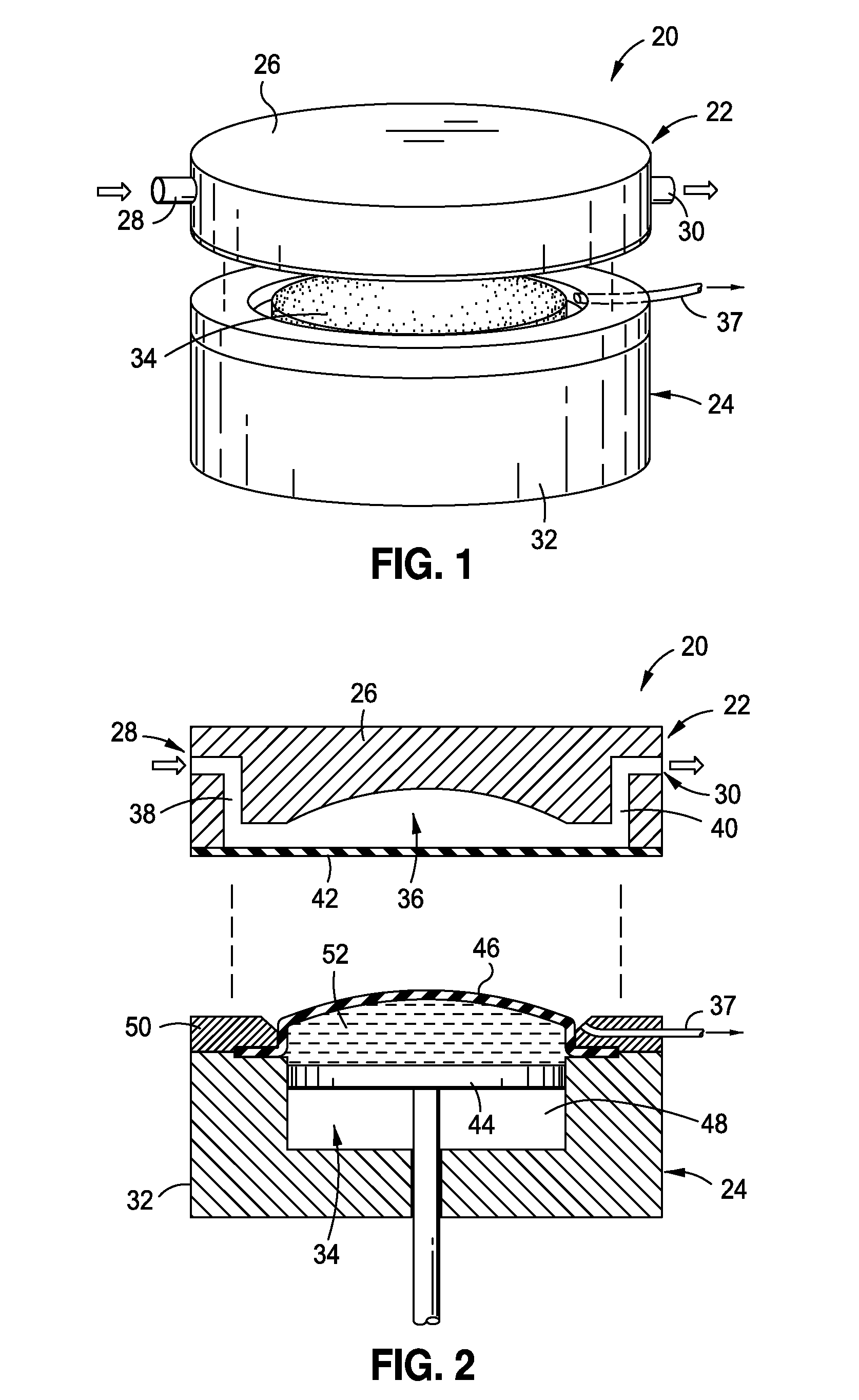
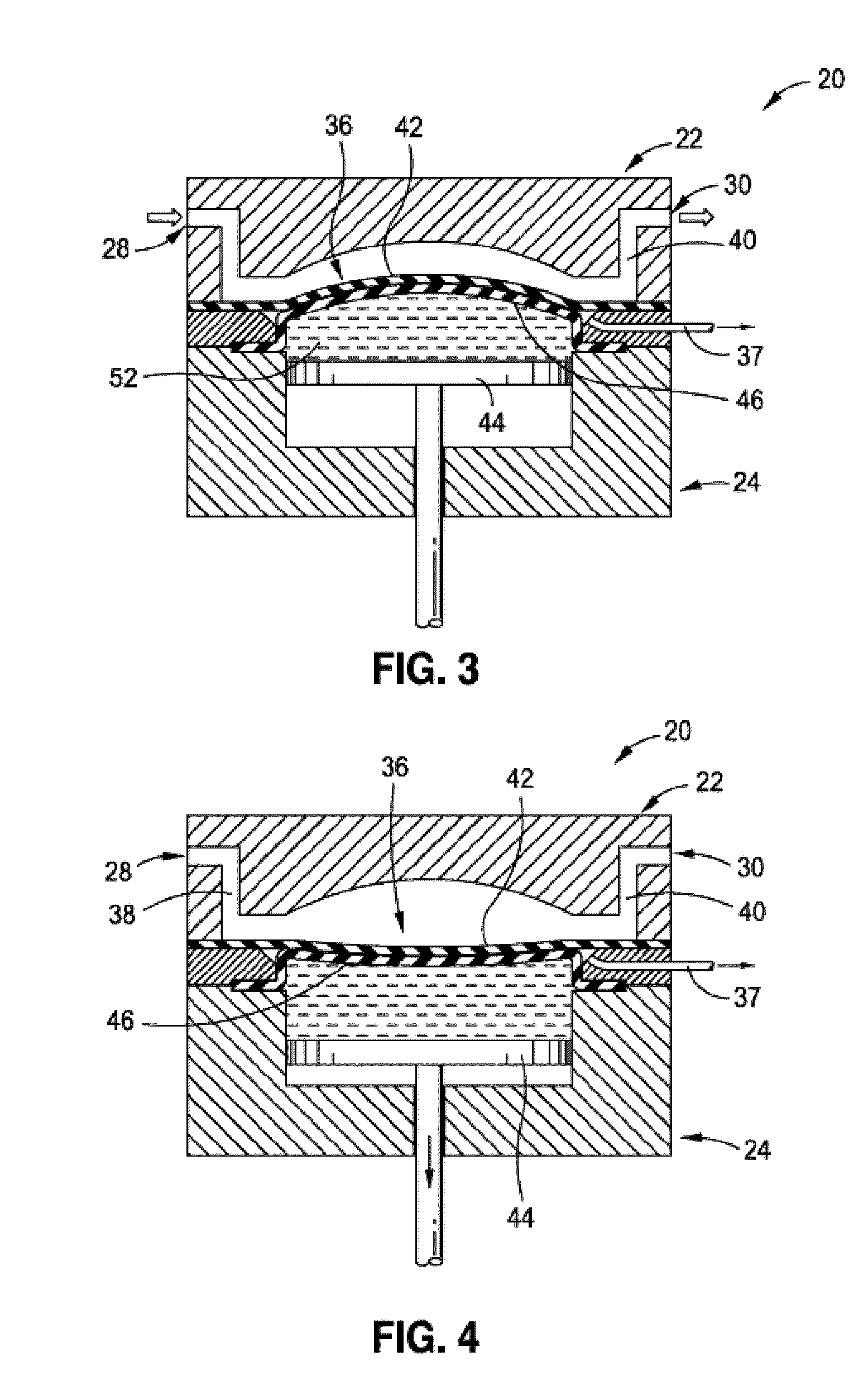
[0029]In general, the invention comprises a fluid pump. The pump has particular utility to the medical field, such as for use in pumping medication from a source to a patient. In general, the pump has a first, disposable portion, and a second, drive portion. The disposable portion is preferably configured as the fluid contacting portion and defines a fluid inlet and outlet and a fluid path there between. The drive portion is configured to engage the disposable portion to cause fluid to be moved from the fluid inlet to the fluid outlet. The disposable portion is configured to be selectively coupled ...


PUM


Abstract

A pump having a disposable fluid contacting portion which defines a fluid inlet and outlet and a fluid path there between. The pump includes a drive portion configured to engage the disposable portion to cause fluid to be moved from the fluid inlet to the fluid outlet. The disposable portion is configured to be selectively coupled to the drive portion. The disposable portion includes a driven membrane which forms a portion of the fluid path, and the drive portion includes a drive membrane. The two membranes are vacuum coupled to each other, whereby movement of the drive membrane causes the driven membrane to move, causing fluid to be pumped through the disposable portion. The pump has particular utility in the medical field for moving fluid from a source to a patient. The pump may include features such as an air-trap, bubble detection, fluid flow controls, and pressure detection.

Description

FIELD OF THE INVENTION[0001]The present invention relates to fluid pumps, especially to medication delivery pumps.BACKGROUND OF THE INVENTION[0002]A wide variety of medication delivery pumps are known. In general, these pumps are configured to deliver a fluid from a source to a patient under pressure.[0003]In order for the pump to be re-usable, at least the portion of the pump which contacts the fluid must be sterilizable. This is difficult for integral pumps where the pumping mechanism and fluid path are part of a single unit. For this reason, pumps have been developed with have a re-usable pumping unit which cooperates with a fluid path element. In this manner, the fluid path element can be separated from the pumping unit for sterilization and reuse.[0004]These reusable pumps, however, suffer from a number of drawbacks. First, many designs are highly complex, resulting in high costs of manufacture and maintenance costs, and low reliability. In addition, the pumps generally suffer ...

Claims


Application Information

Patent Timeline
Patent Type & Authority Patents(United States)
IPC IPC(8): F04B35/02F16J3/02F04B23/06F16J3/06
CPCA61M5/14224A61M5/14593A61M5/1413A61M2205/106A61M2205/122A61M2205/128A61M2005/14513F04B43/021
Inventor BUTTERFIELD, ROBERT D.
Owner CAREFUSION 303 INC
Why Eureka
Try Eureka