Connector

a technology of connectors and connectors, applied in the direction of lighting support devices, coupling device connections, lighting and heating apparatus, etc., can solve the problems of lowering the conductor of each fluorescent tube and the contact stability between the contacts of the above-described backlight connectors, and achieve the effect of maintaining contact stability

Inactive Publication Date: 2012-01-03
JAPAN AVIATION ELECTRONICS IND LTD
View PDF13 Cites 3 Cited by
  • Summary
  • Abstract
  • Description
  • Claims
  • Application Information

AI Technical Summary

Benefits of technology

[0014]The present invention has been made in view of these circumstances, and an object thereof is to provide a connector which makes it possible to maintain contact stability between an object to be connected and a contact.
[0016]With the arrangement of the connector according to the present invention, the pair of operation portions connected to the pair of pressing portions are linked by the first linking portion and the second linking portion, which are opposed to each other, and hence reaction force from the contact, which acts on the pair of pressing portions, is dispersed through the first linking portion and the second linking portion via the pair of operation portions. As a result, the space between the pressing portions is less liable to be increased.
[0023]According to this invention, it is possible to maintain the contact stability between the object to be connected and the contact.

Problems solved by technology

Therefore, there is a fear that the contact stability between the contacts of the above-described backlight connector and the conductor of each fluorescent tube is lowered.

Method used


Image

  • Connector
  • Connector
  • Connector

Examples


first embodiment

[0052]A description will be given of a connector according to the present invention with reference to FIGS. 1 to 13.

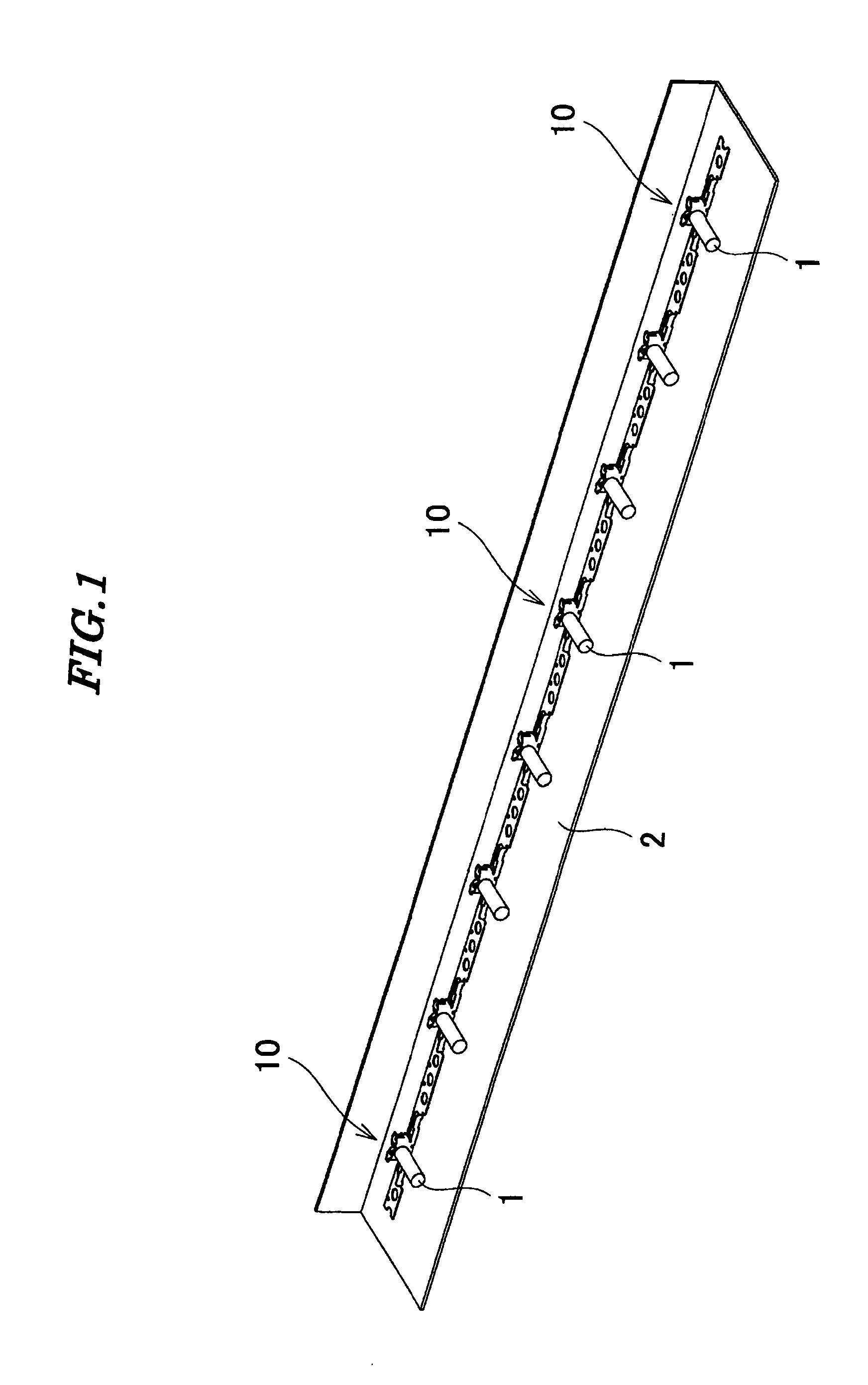
[0053]As shown in FIG. 1, connectors 10 are fixed on a chassis (another object to be connected) 2 at equally-spaced intervals. The connectors 10 electrically connect fluorescent tubes (object to be connected) 1 and the chassis 2.

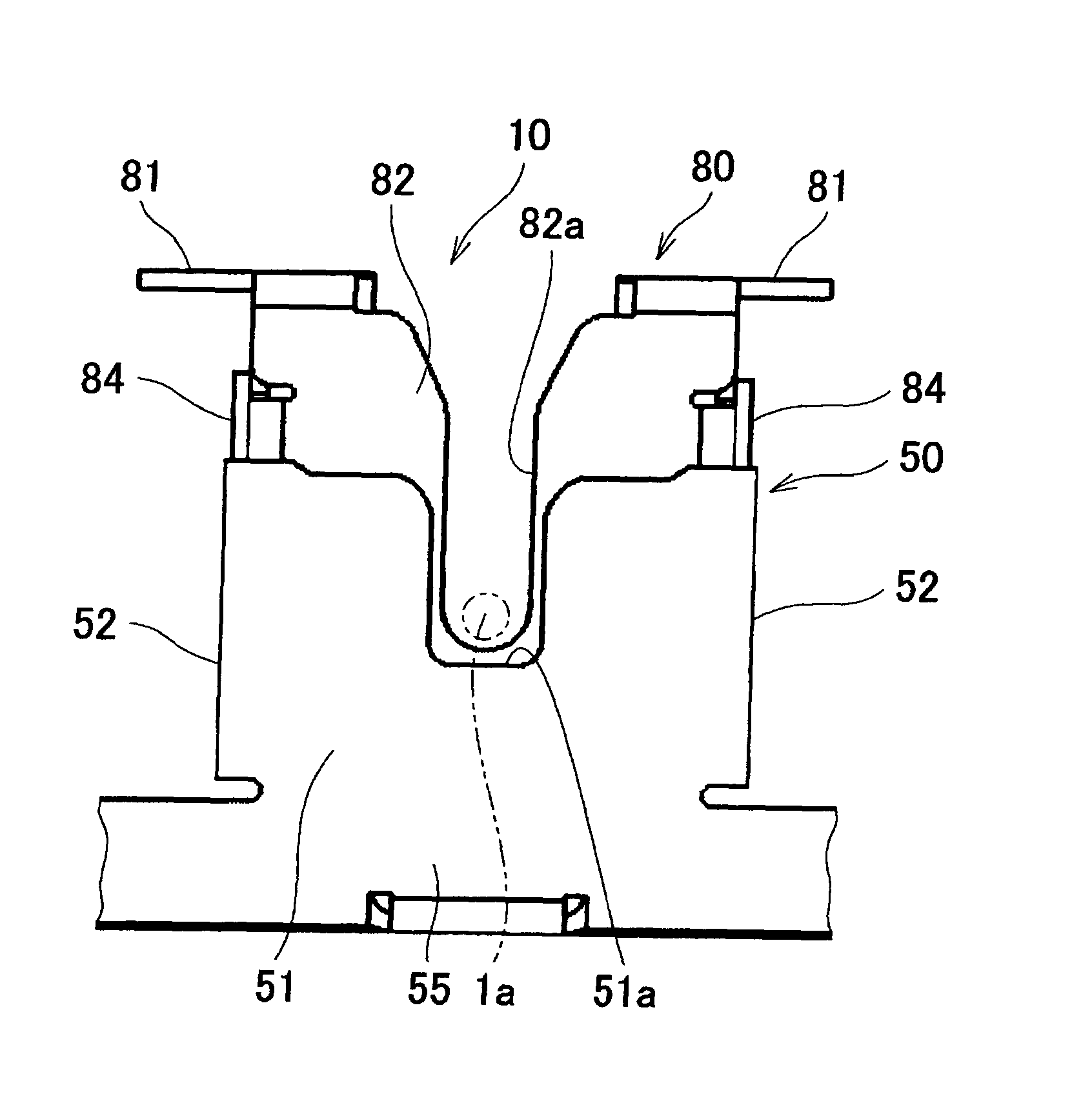
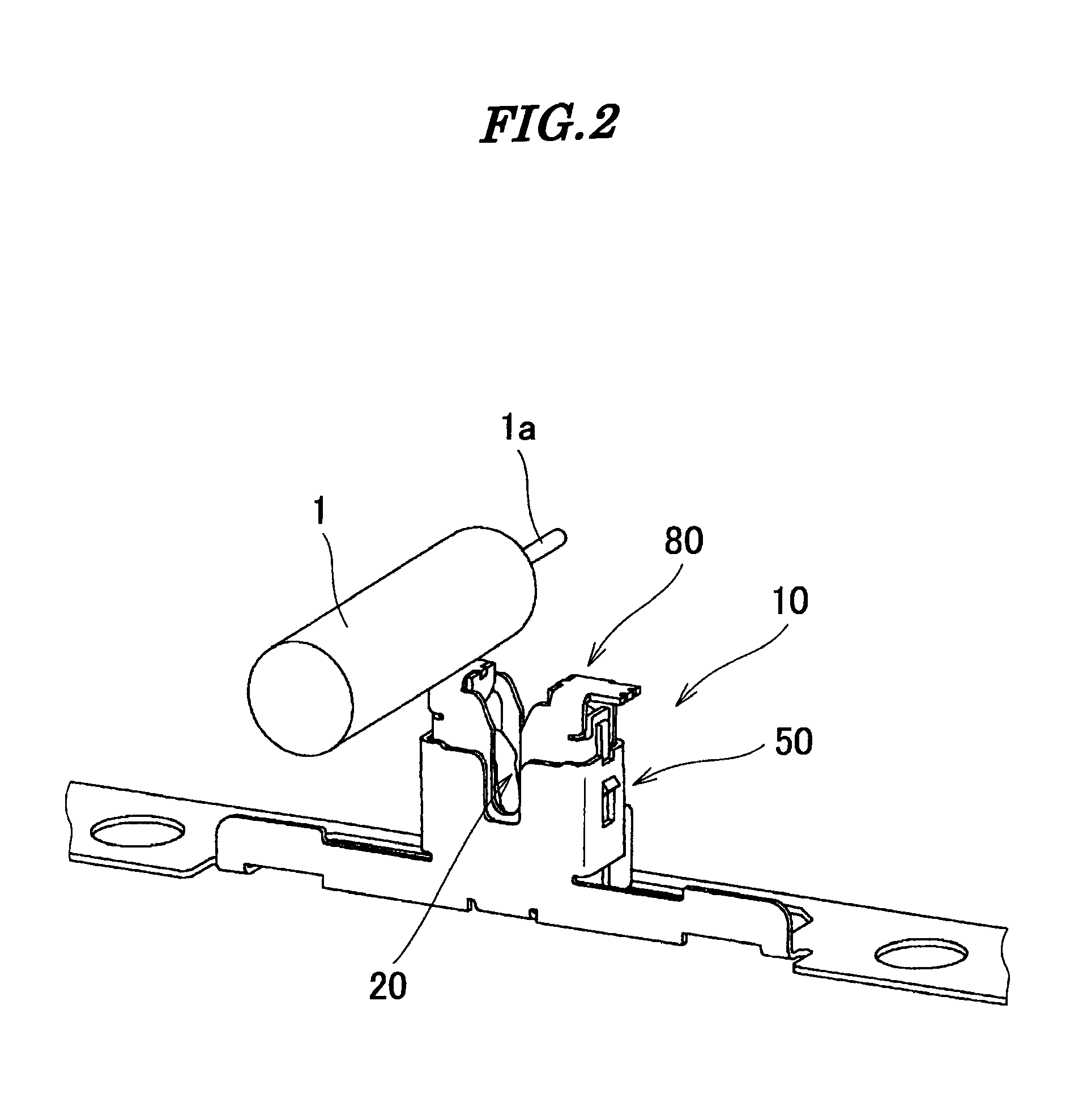
[0054]As shown in FIGS. 2 and 3, each connector 10 is comprised of a contact 20, a housing (supporting member) 50, and an operation member 80.

[0055]As shown in FIGS. 4 and 12, the contact 20 includes a bottom plate portion 21, a pair of spring portions 22, a pair of contact portions 23, a pair of engaging portions 24, a pair of guide portions 25, a pair of linking portions 26, a pair of connection portions 27, a linking portion 28, and a pair of supporting portions 29.

[0056]The bottom plate portion 21 is placed on the chassis 2. The pair of spring portions 22 are continuous with the bottom plate portion 21, and extend upward (upward in FIG. 12 ...

second embodiment

[0077]Next, a description will be given of a connector according to the present invention with reference to FIGS. 14 to 22.

[0078]Component parts identical to those of the connector according to the first embodiment are designated by identical reference numerals, and detailed description thereof is omitted, while only main component parts different in construction from those of the first embodiment will be described hereinafter.

[0079]As shown in FIGS. 14 and 15, connectors 210 are fixed to the cassis 2 at equally-spaced intervals. The connectors 210 are used in combination with the connectors 10 of the first embodiment, and electrically connect the fluorescent tubes 1 and a printed circuit board 6. The connector 10 of the first embodiment is used for connection with one of the pair of terminal portions 1a of the fluorescent tube 1, and the connector 210 of the second embodiment is used for connection with the other of the pair of terminal portions 1a of the fluorescent tube 1.

[0080]A...

third embodiment

[0109]Next, a description will be given of an operation member of a connector according to the present invention with reference to FIGS. 23 and 24.

[0110]Component parts identical to those of the connector according to the first embodiment are designated by identical reference numerals, and detailed description thereof is omitted, while only main component parts different in construction from those of the first embodiment will be described hereinafter.

[0111]Although in the operation member 80 of the first embodiment, each operation portion 81 and the associated pressing portion 86 are connected by engagement, in an operation member 380 of the third embodiment, as shown in FIGS. 23 and 24, each pressing portion 386 continuously extends from the associated operation portion 81, and the operation portion 81 and the pressing portion 386 are integrally connected. The pressing portions 386 extend in parallel to side portions 384.

[0112]Further, although in the first embodiment, the operatio...


PUM

PropertyMeasurementUnit
bendingaaaaaaaaaa
elasticityaaaaaaaaaa
fluorescentaaaaaaaaaa

Abstract

A connector which has a high level of contact stability. An operation member is formed by blanking and bending a metal plate. First and second linking portions that are disposed in a manner opposed to each other to connect a pair of operation portions are in an arrangement in which the first and second linking portions sandwich a pair of operation portions when the operation member is in a developed state. When the operation member is in a completed state, the first and second linking portions connecting the are bent at right angles with respect to the pair of operation portions, respectively.

Description

BACKGROUND OF THE INVENTION[0001]1. Field of the Invention[0002]This invention relates to a connector.[0003]2. Description of the Related Art[0004]Conventionally, there has been proposed a connector for backlight (hereinafter referred to as a “backlight connector”) which comprises a main body and a slider (see Japanese Laid-Open Patent Publication (Kokai) No. 2006-244749 (Paragraphs 0014 to 0017, and FIGS. 2 and 3)).[0005]The main body includes a pair of contacts, a plate portion, a pair of guide portions and a pair of side plates. Each contact has elasticity. Each contact is substantially U-shaped in plan view, and has an outer wall portion and an inner wall portion. The outer wall portion has an outer surface thereof formed with a protuberance which protuberates outward. The plate portion receives a fluorescent tube. The guide portions rise from opposite side edges of the plate portion, respectively. Each side plate is formed with a long narrow slot. The slot extends in a directio...

Claims


Application Information

Patent Timeline
Patent Type & Authority Patents(United States)
IPC IPC(8): H01R33/02
CPCH01R13/193H01R33/02Y10T29/49204H01R43/16A61F5/0102A61F5/0123A61F5/042A61F5/30A61F5/32
Inventor URANO, TETSU
Owner JAPAN AVIATION ELECTRONICS IND LTD
Why Eureka
Try Eureka