Connector and connector assembly

a technology of connectors and connectors, applied in the direction of coupling contacts, coupling bases/cases, coupling device connections, etc., can solve the problems that the terminal stability of the two connectors becomes more important, and achieve the effect of reducing the height of the connector and reducing the contact area between the terminals of the two connectors

Active Publication Date: 2018-10-11
MOLEX INC
View PDF1 Cites 0 Cited by
  • Summary
  • Abstract
  • Description
  • Claims
  • Application Information

AI Technical Summary

Benefits of technology

[0006]As the height of the connector is reduced, the contact area between the terminals of the two connectors is reduced. Therefore, the contact stability of the terminals of the two connectors becomes a more important issue.

Problems solved by technology

Therefore, the contact stability of the terminals of the two connectors becomes a more important issue.

Method used


Image

  • Connector and connector assembly
  • Connector and connector assembly
  • Connector and connector assembly

Examples


Embodiment Construction

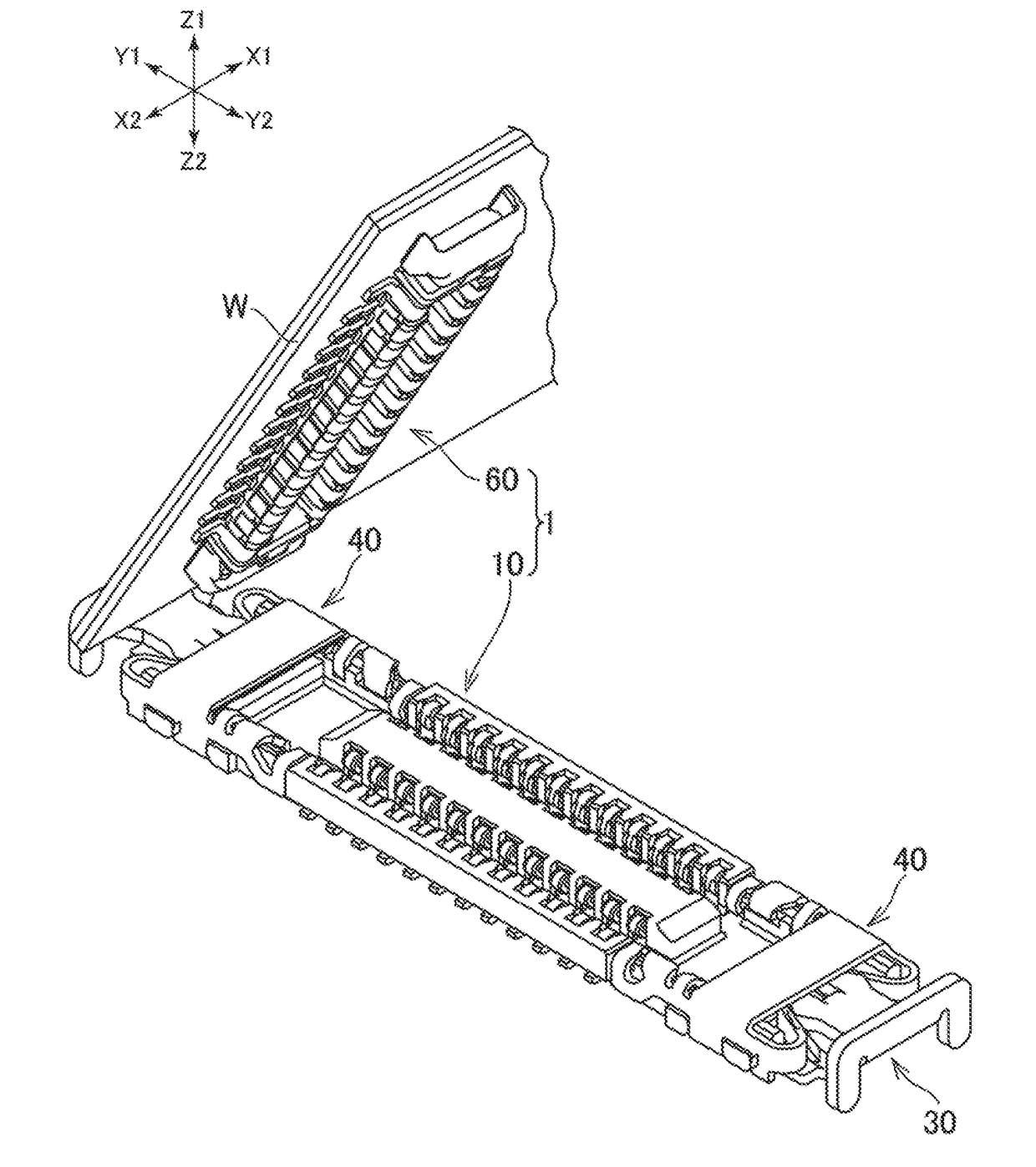
[0028]The connector and the connector assembly proposed in the present disclosure are described below. The connector assembly of the present disclosure includes a connector to which a plurality of electric wires or circuit boards are connected, and a connector connected to a circuit board. The circuit board is, for example, a printed wiring board (Printed Circuit Board), a flexible flat cable (Flexible Flat Cable), a flexible printed wiring board (Flexible Printed Circuit), and the like, used for electronic equipment and the like, but any type of circuit board may be used. Further, the electric wire may be any type of electric wire such as a single core electric wire or a coaxial electric wire. A plurality of electric wires may be arranged in one direction.

[0029]In the present disclosure, a connector assembly including a connector connected to one circuit board and a connector connected to another circuit board is described as one example of a connector assembly. By mating the two c...


PUM


Abstract

A receptacle connector is provided with a slider and a first securing metal fitting. The slider can slide between a locking position where the slider locks a plug connector and a lock releasing position where the slider is separated from the plug connector to an outer side in a longitudinal direction such that locking of the plug connector is released. The first securing metal fitting has the hook, and the slider has the first engageable part that engages with the hook.

Description

RELATED APPLICATIONS[0001]This application claims priority to U.S. Provisional Patent Application No. 62 / 482,775, filed Apr. 7, 2017 and to Japanese Application No. 2017-125303, filed Jun. 27, 2017, both of which are incorporated herein by reference in their entirety.TECHNICAL FIELD[0002]The present disclosure relates to a connector and a connector assembly.BACKGROUND ART[0003]Conventionally, a connector for connecting two circuit boards facing each other is used (for example, refer to Patent Document 1).[0004]The two circuit boards are connected by mutually mating a connector attached to one circuit board and a connector attached to the other circuit board. In conjunction with the downsizing and thinning of electronic devices, reduction in height of this kind of connector is advancing.[0005]Patent Document 1: JP2015-60764ASUMMARY[0006]As the height of the connector is reduced, the contact area between the terminals of the two connectors is reduced. Therefore, the contact stability ...

Claims


Application Information

Patent Timeline
Patent Type & Authority Applications(United States)
IPC IPC(8): H01R12/70H01R12/52H01R12/71
CPCH01R12/7058H01R12/52H01R12/716H01R13/46H01R13/629H01R13/639H01R24/00H01R12/707H01R13/24
Inventor TANAKA, DAIKINAITO, YUJIYOSHIKAWA, NAOTO
Owner MOLEX INC
Why Eureka
Try Eureka