Firearm attachment locking system

Active Publication Date: 2012-01-10
SUREFIRE LLC
View PDF43 Cites 58 Cited by
  • Summary
  • Abstract
  • Description
  • Claims
  • Application Information

AI Technical Summary

Problems solved by technology

However, with any type of blank firing adapter, consideration must be made in the event that real ammunition is accidentally used.

Method used


Image

  • Firearm attachment locking system
  • Firearm attachment locking system
  • Firearm attachment locking system

Examples


Embodiment Construction

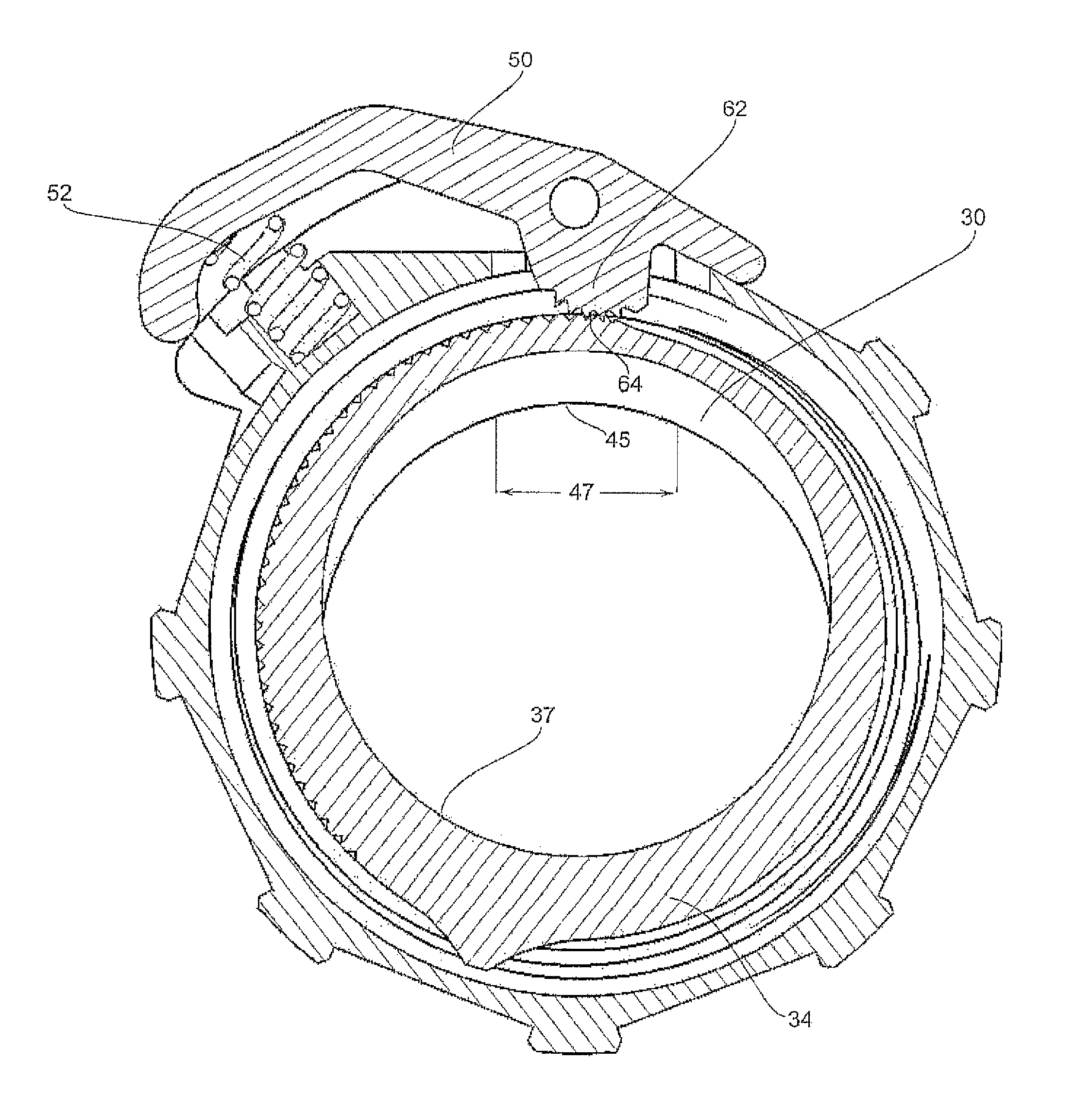
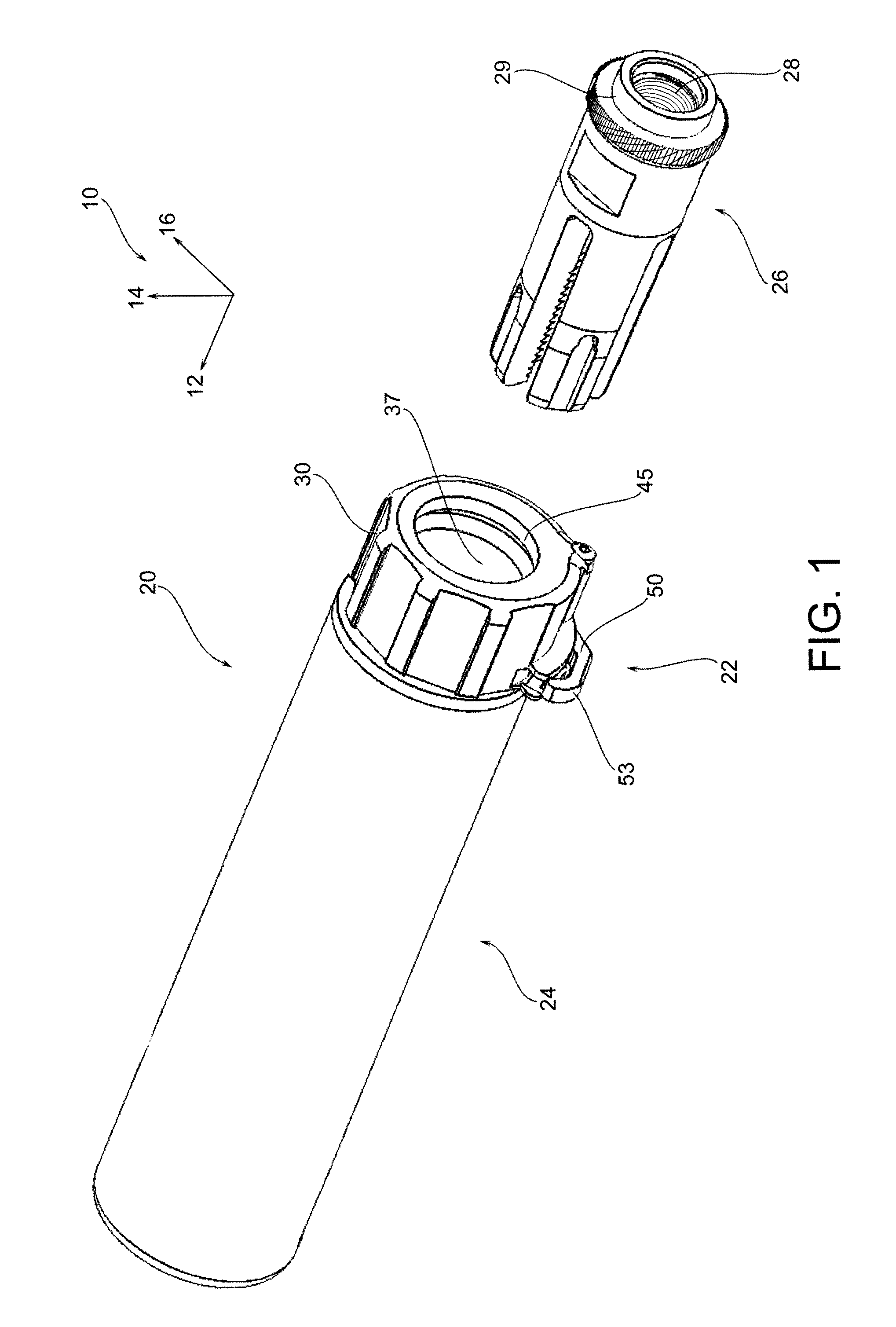
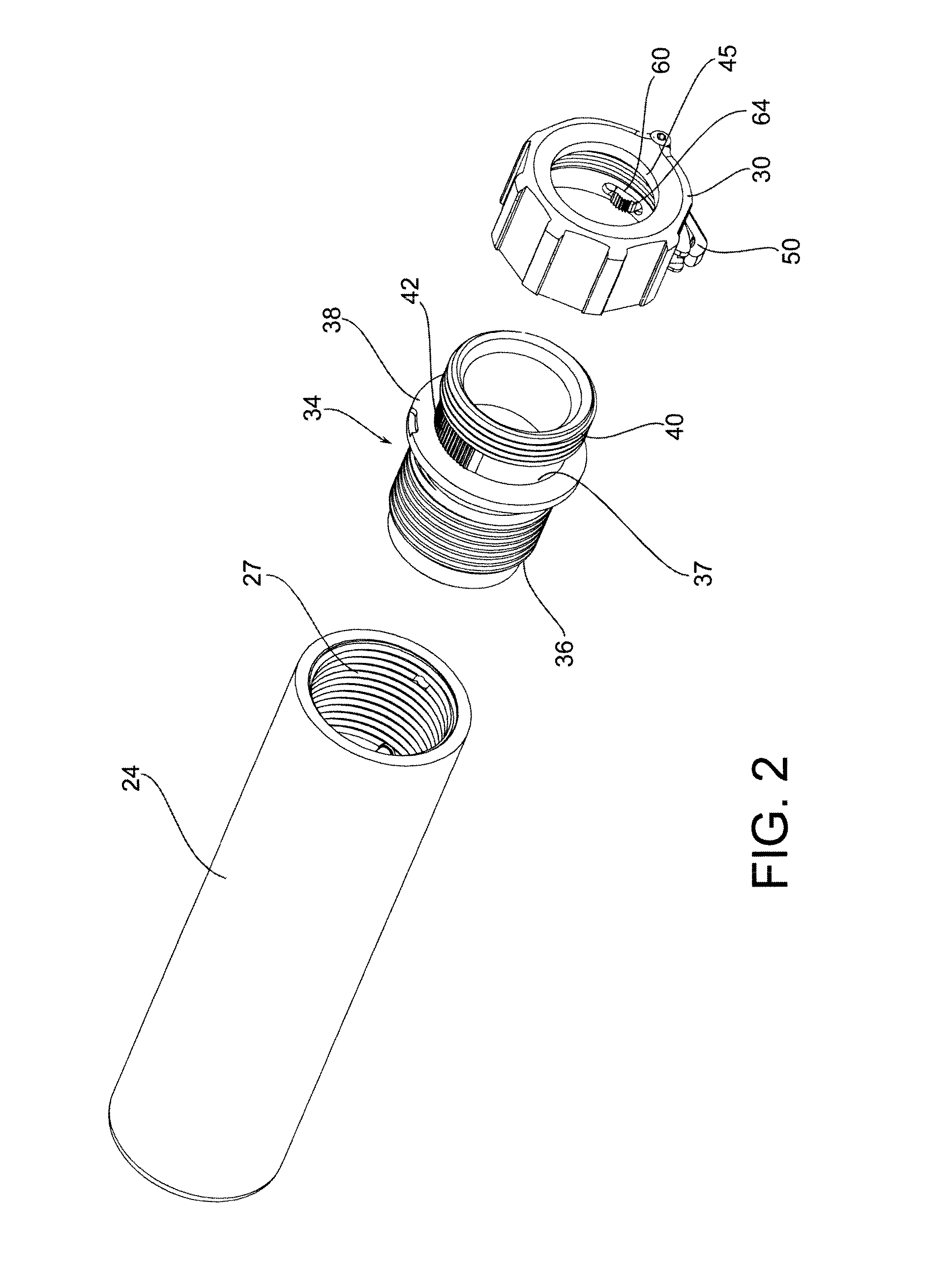
[0042]As shown in FIG. 1, there is a firearm attachment 20 such as a suppressor or blank firing adapter which in general comprises a locking assembly 22 and a suppressor body 24. The firearm attachment 20 is operatively configured to be attached to a muzzle 26 of a firearm. FIG. 1 generally shows only a muzzle flash suppressor which is configured to be attached to a barrel by way of the threaded portion 28. An axes system 10 is defined where the axis 12 defines a longitudinal forward direction, the axis 14 defines a vertical direction, and the axes 16 defines a lateral direction pointing to the right-hand lateral direction by reference of the operator of the firearm. It should be further noted that the axes 14 and 16 both generally indicate a radial direction with reference to the centerline of the suppressor body 24. Further, a tangential direction is defined as a general direction perpendicular the radial direction.

[0043]In general, the locking assembly 22 can be utilized in a var...


PUM


Abstract

A locking system for a firearm attachment. The locking system having a rotating lock ring having a lock-and-release lever rotatably mounted thereto. The lock-and-release lever having a lock engagement surface optimally configured to forcefully engage a locking surface when in a locked orientation. The locking ring having a nonconcentric engagement surface that repositions in a radial direction when the locking ring rotates and the nonconcentric engagement surface is configured to engage the muzzle of a firearm for locking the muzzle attachment thereto.

Description

BACKGROUND OF THE DISCLOSURE[0001]Attachments to the muzzle of a firearm generally must be secured in a consistent and reliable manner for proper operation. Whether the attachments are for live ammunition or blank rounds, the attachment mechanism should be intuitive to the user and provide proper engagement to avoid a loose attachment to the muzzle of a firearm.[0002]Suppressors are attached to firearms for suppressing sound and in some cases flash associated with the expanding combusting gases exiting from the muzzle. In general, it is desirable to have a suppressor that can be attached to the muzzle of a firearm quickly and easily in a repeatable manner so as not to modify the “zero” bullet impact of the firearm.[0003]Other attachment fixtures can be utilized to emulate a suppressor or otherwise be provided for certain applications, such as a blank firing adapter, flash suppressor, compensator or other devices configured to be attached to the muzzle of a firearm. A blank firing ad...

Claims


Application Information

Patent Timeline
Patent Type & Authority Patents(United States)
IPC IPC(8): F41A21/00F41A21/32
CPCF41A21/325F41A21/26
Inventor DUECK, BARRY W.HONIGMANN, KARL
Owner SUREFIRE LLC
Why Eureka
Try Eureka