Electrical box template

a box template and electric box technology, applied in the field of electric box templates, can solve the problem of taking time and effort to match the shap

Inactive Publication Date: 2012-01-24
GUZALLIS JON
View PDF20 Cites 7 Cited by
  • Summary
  • Abstract
  • Description
  • Claims
  • Application Information

AI Technical Summary

Problems solved by technology

This takes time and effort to match the shapes.
Likewise, if the builder is not skilled, mistakes can happen causing the opening to be larger than the box, off center from the box, or smaller than the box.
In each of these situations, the builder needs to spend time and money to repair the mistake.

Method used


Image

  • Electrical box template
  • Electrical box template
  • Electrical box template

Examples


Embodiment Construction

[0023]Persons of ordinary skill in the art will realize that the following disclosure is illustrative only and not in any way limiting. Other embodiments of the disclosure will readily suggest themselves to such skilled persons having the benefit of this disclosure.

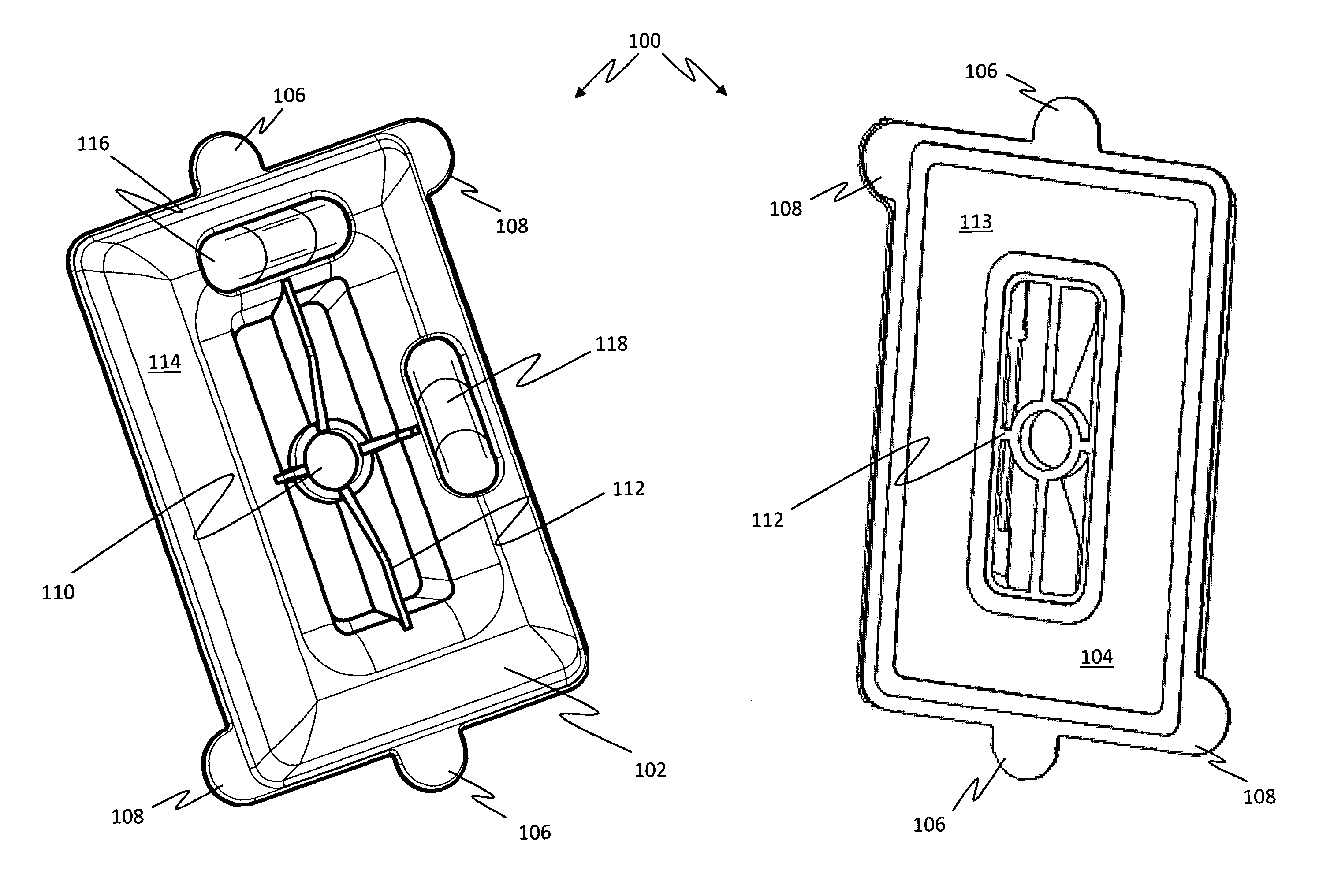
[0024]The present disclosure is an electrical box template that can be utilized to accurately position an opening in a wall for an electrical box. The template is positioned centrally in the desired location using the centering orifice and levels the electrical box template using the levels. The user can then trace around the exterior of the electrical box template, marking the shape on the wall. The user can then cut out the shape for accessing the electrical box disposed in the interior of the wall.

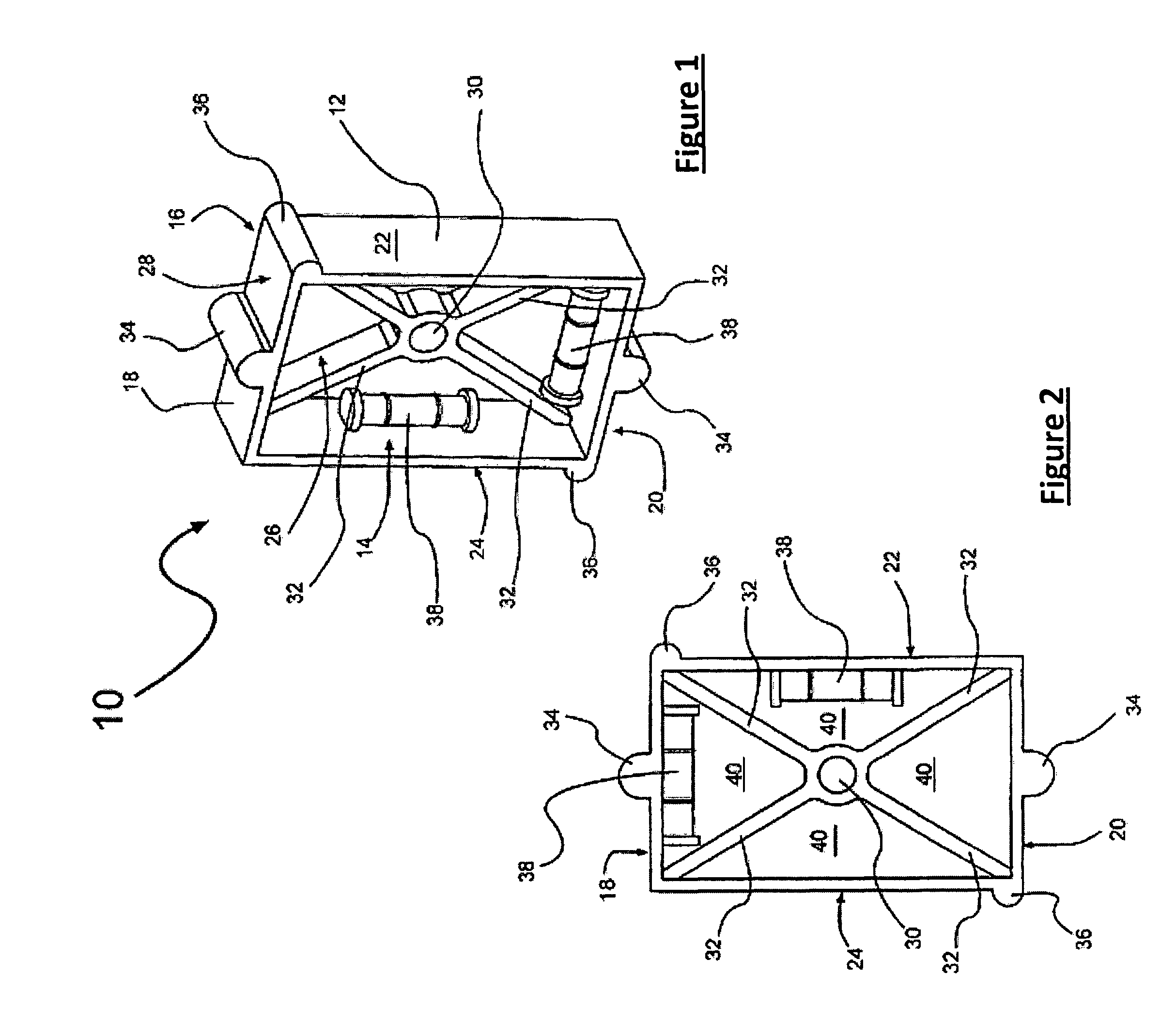
[0025]Referring to FIGS. 1 and 2, a perspective front view of an exemplary electrical box template 10 is illustrated in FIG. 1 and a front view of the electrical box template 10 is illustrated in FIG. 2. The electrical box te...


PUM


Abstract

An electrical box template, an electrical box template extension device and a method for utilizing the electrical box template and an electrical box template extension device is provided and includes a template body having a template perimeter, a template back and a template front, wherein the template front includes, a front surface protruding from the template front and located adjacent at least a portion of the template perimeter, a centering structure located in a center portion of the template body and defining a centering orifice and at least one interior support located between said centering structure and the protruding front surface.

Description

RELATED APPLICATIONS[0001]This application is a Continuation-In-Part of, and claims benefit of, U.S. Utility patent application Ser. No. 12 / 151,750 filed May 7, 2008, now abandoned the contents of which are incorporated by reference herein it its entirety.BACKGROUND OF THE INVENTION[0002]When remodeling or constructing homes, offices and commercial buildings, electrical outlet boxes and switch boxes are installed throughout the structure. Many times the boxes are usually installed on a stud at a uniform distance from the floor and in a uniform location along the stud. Sheet rock (or drywall or other wall material) is generally installed on the walls in preparation for finishing the rooms. When the sheet rock is installed the boxes are then covered. The builder must then make an opening in the sheet rock and cut the opening appropriately for installing the outlets or switches within the boxes.[0003]When the builder begins to shape the opening for receiving the outlets or switches, th...

Claims


Application Information

Patent Timeline
Patent Type & Authority Patents(United States)
IPC IPC(8): G01D21/00
CPCH02G1/00H02G2200/30
Inventor GUZALLIS, JON
Owner GUZALLIS JON
Why Eureka
Try Eureka