Hybrid orthodontic appliance

a technology of orthodontic appliances and brackets, applied in the field of orthodontic appliances, can solve the problems of lack of rigidity and structure, flexible, easily cracked and broken,

Active Publication Date: 2012-02-21
TORTORICI JOSEPH
View PDF19 Cites 93 Cited by
  • Summary
  • Abstract
  • Description
  • Claims
  • Application Information

AI Technical Summary

Problems solved by technology

This appliance is preferably transparent, but it lacks rigidity and structure, and is thereby flexible and easily cracked and broken.

Method used


Image

  • Hybrid orthodontic appliance
  • Hybrid orthodontic appliance
  • Hybrid orthodontic appliance

Examples


Embodiment Construction

[0025]Preferred embodiments of the present invention are described in detail with reference to the accompanying drawings. In the drawings, the same or similar elements are denoted by the same or similar reference numerals even though they are depicted in different drawings. Detailed descriptions of constructions or processes known in the art may be omitted to avoid obscuring the subject matter of the present invention.

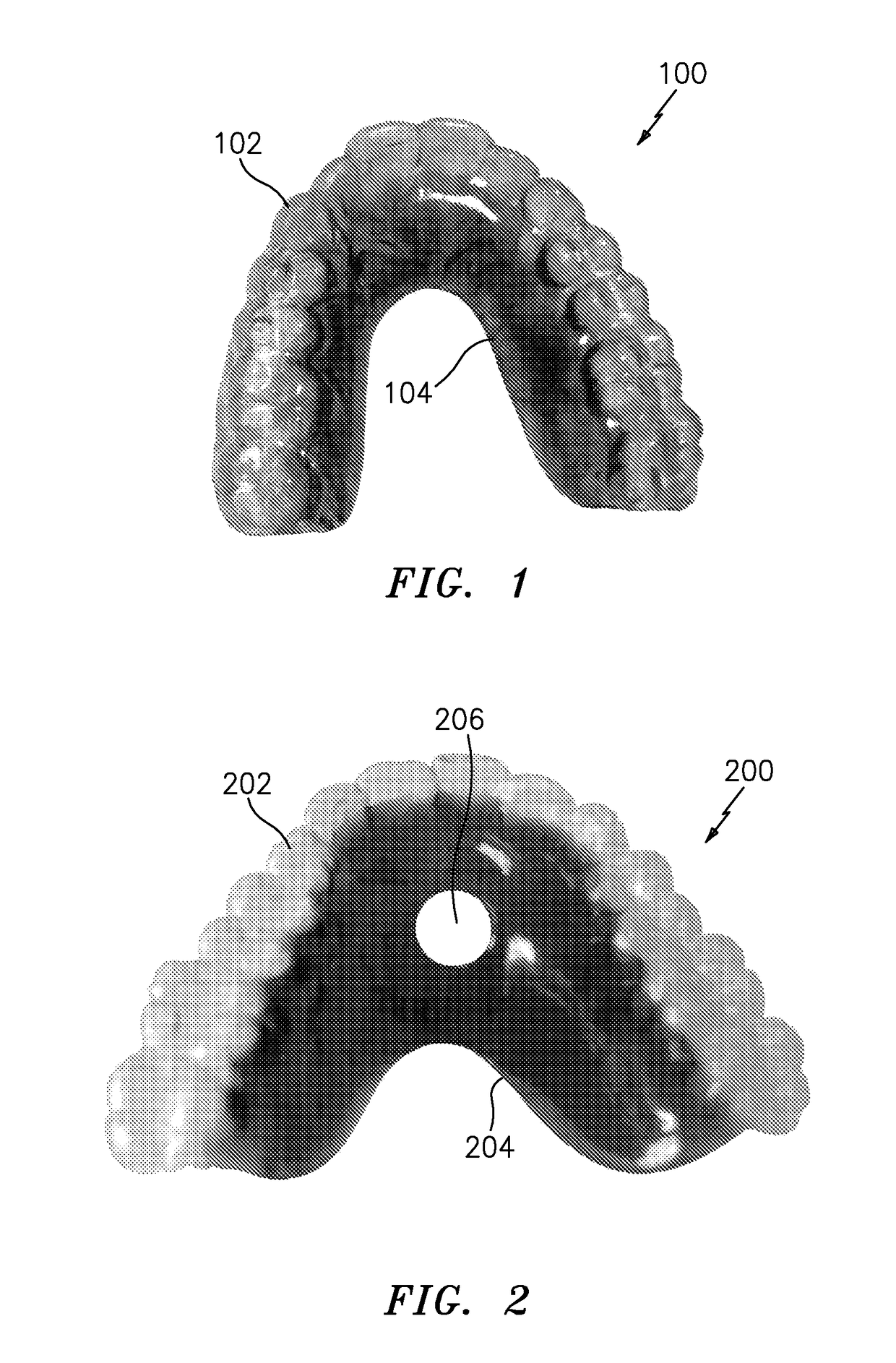
[0026]Referring initially to FIG. 1, a diagram illustrates a hybrid retaining orthodontic appliance, according to an embodiment of the present invention. A hybrid retaining orthodontic appliance 100 for use on a patient's maxillary (upper) dental arch is illustrated, however appliances may be suited for both maxillary and mandibular (lower) arches. Hybrid retaining orthodontic appliance 100 has a dental encasing component 102 specifically shaped to overlay the teeth and a portion of the palate of the patient. In order to encase the teeth of the patient, dental encasing...


PUM


Abstract

An orthodontic appliance is provided for controlling positioning of a patient's teeth. The appliance includes at least one dental encasing component formed to overlay at least one of the patient's teeth and at least a portion of a palate of the patient. The at least one dental encasing component has a lingual surface and a labial surface. The appliance also includes at least one rigid component fused to an entire length of the lingual surface of the at least one dental encasing component and over a portion of the at least one dental encasing component overlaying a portion of the palate of the patient.

Description

PRIORITY[0001]This application claims priority under 35 U.S.C. §119(e) to a Provisional Patent Application filed in the USPTO on Nov. 21, 2007 and assigned Ser. No. 60 / 989,617, the disclosure of which is incorporated herein by reference.BACKGROUND OF THE INVENTION[0002]1. Field of the Invention[0003]The present invention relates to orthodontic appliances, and more particularly, to hybrid orthodontic appliances with improved rigidity and structure for controlling the position of a patient's teeth.[0004]2. Description of the Related Art[0005]Removable orthodontic appliances are well known in the art for use before, during and after orthodontic treatment, for the purpose of moving and retaining the positions of an orthodontic patient's teeth. The appliances are removable and worn by patients in accordance with instructions from an orthodontist.[0006]Removable orthodontic appliances may be constructed for use on both upper and lower dental arches and have typically been formed using var...

Claims


Application Information

Patent Timeline
Patent Type & Authority Patents(United States)
IPC IPC(8): A61C3/00
CPCA61C7/08A61C7/10
Inventor TORTORICI, JOSEPH
Owner TORTORICI JOSEPH
Why Eureka
Try Eureka