PCB bridge connector for connecting PCB devices

a technology of pcb devices and bridge connectors, which is applied in the direction of coupling device connections, printed circuits, electrical apparatus, etc., can solve the problems of inefficient storage and transportation of such assemblies, waste of pcb materials, and the need to discard the entire assembly, so as to facilitate the repair and use of ir touch sensor frames using four pcb frame sections. , the effect of reducing the cos

Inactive Publication Date: 2012-02-21
CNPLUS
View PDF31 Cites 35 Cited by
  • Summary
  • Abstract
  • Description
  • Claims
  • Application Information

AI Technical Summary

Benefits of technology

[0009]When the bridge connector is attached to a printed circuit board (PCB), the press-fit pins extend into, and engage corresponding plated through holes in the PCB. The press-fit pins exert enough retention force to mechanically couple two PCB frame sections. The PCB frame sections are electrically connected through the press-fit pins and corresponding signal conductors of the bridge connector. A bridge connector attached at each corner of an IR touch sensor frame assembly allows the assembly to be solidly assembled from four sections of PCB: a top, bottom, left, and right PCB frame section. Prototyping, shipping and repairing an IR touch sensor frame using four PCB frame sections is easier and less expensive than with a one-piece IR touch sensor frame.

Problems solved by technology

The center cut-out portion of PCB must be discarded, resulting in expensive waste of PCB material.
Due to the rectangular shape and unused center space, storing and shipping of such assemblies is inefficient.
Furthermore, if a component (such as a receiver or transmitter) is damaged, the entire assembly must be discarded.

Method used


Image

  • PCB bridge connector for connecting PCB devices
  • PCB bridge connector for connecting PCB devices
  • PCB bridge connector for connecting PCB devices

Examples


Embodiment Construction

[0034]Reference will now be made in detail to some embodiments of the invention, examples of which are illustrated in the accompanying drawings.

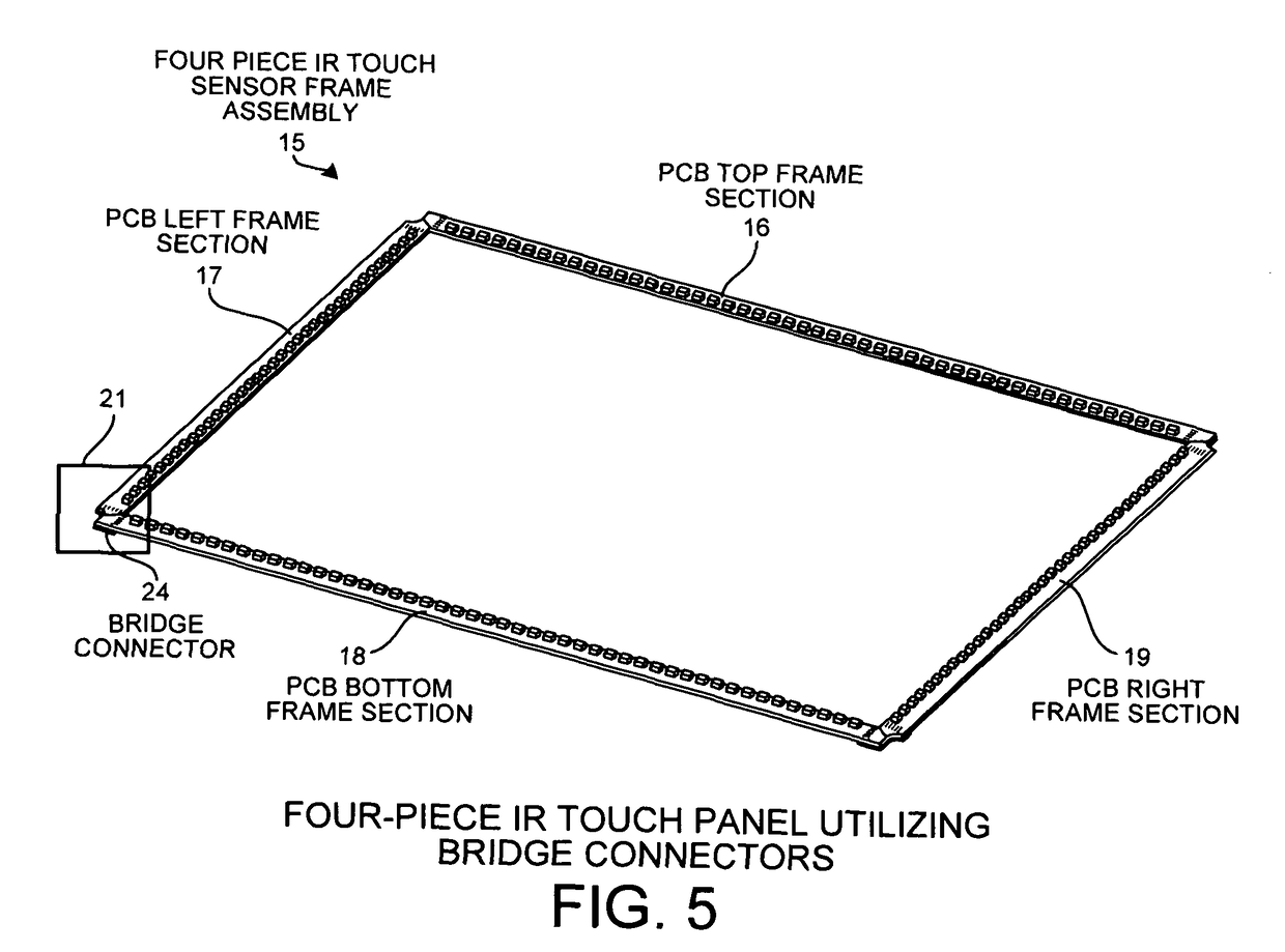
[0035]FIG. 5 is a view of the top side of a four-piece IR touch frame assembly 15. A series of IR LED transmitters are disposed on PCB top frame section 16 and arranged so as to correspond to a series of IR LED receivers disposed on PCB bottom frame section 18. Another series of IR LED transmitters are disposed on PCB left frame section 17 and arranged so as to correspond to a series of IR LED receivers disposed on PCB right frame section 19. PCB left frame section 17 and PCB bottom frame section 18 are coupled together, through bridge connector 24, in an L-shaped arrangement at a corner section 21 of the IR touch frame assembly 15.

[0036]Example dimensions of a four-piece IR touch sensor frame assembly are 8.5 inches in a vertical dimension and 11 inches in a horizontal dimension. The frame assembly 15 is arranged in a window shape so that a...


PUM


Abstract

A bridge connector made of PCB material has a first plurality of press-fit pins on one portion of the bridge connector and a second plurality of press-fit pins on another portion of the bridge connector. Within the connector is a set of signal conductors. Each conductor connects a press-fit pin of the first plurality of press-fit pins to a corresponding press-fit pin of the second plurality of press-fit pins. When the connector is attached to a printed circuit board (PCB), the press-fit pins extend into and engage corresponding plated through holes in the PCB. The press-fit pins exert enough retention force to mechanically couple two PCB frame sections. The PCB frame sections are electrically connected through the press-fit pins and corresponding signal conductors of the bridge connector. A bridge connector attached at each corner of an infrared touch sensor frame assembly allows the assembly to be solidly assembled from four sections of PCB: a top, bottom, left, and right PCB frame section.

Description

CROSS REFERENCE TO RELATED APPLICATION[0001]This application claims the benefit under 35 U.S.C. §119 of provisional application Ser. No. 61 / 110,042, entitled “Connector Having Printed Circuit Board Portion”, filed Oct. 31, 2008. The subject matter of provisional application Ser. No. 61 / 110,042 is incorporated herein by reference.TECHNICAL FIELD[0002]The described embodiments relate to PCB bridge connectors, and, more specifically, bridge connectors for connecting two sections of an infrared touch sensor frame assembly.BACKGROUND INFORMATION[0003]FIG. 1 (Prior Art) is a stylized view of an infrared (IR) touch sensor frame assembly 1. A printed circuit board (PCB) frame body 2 has a portion of PCB material cut out of the center of the body such that the remaining PCB material forms a single-piece, four-sided frame. IR light emitting diode (LED) transmitters and receivers are disposed on the PCB frame body 2 for touch sensing. A series of X-axis IR LED transmitters 3 are arranged on on...

Claims


Application Information

Patent Timeline
Patent Type & Authority Patents(United States)
IPC IPC(8): H01R31/08
CPCH01R12/523H01R12/585H01R31/08H05K1/142H05K1/141H05K3/308H05K2201/1059
Inventor JEON, MYOUNGSOO
Owner CNPLUS
Why Eureka
Try Eureka