Appliance with a vacuum-based reverse airflow cooling system using one fan

a reverse airflow cooling and vacuum technology, applied in the field of applications, can solve the problems of oven doors being too hot to serve, control panel and fan use desirable space, and blowing air down the back of the oven units

Active Publication Date: 2012-03-27
HAIER US APPLIANCE SOLUTIONS INC
View PDF54 Cites 19 Cited by
  • Summary
  • Abstract
  • Description
  • Claims
  • Application Information

AI Technical Summary

Problems solved by technology

The fans may blow the air down the back of the oven units.
One disadvantage of the current dual-cavity oven design is that the control panel and fans use desirable space that could be used for oven capacity.
Another disadvantage of the current dual-cavity oven design is that the oven doors prove too hot to serve as a suitable site for the control panel.
The control panel can be damaged and malfunction because of the excessive heat of the oven door.

Method used


Image

  • Appliance with a vacuum-based reverse airflow cooling system using one fan
  • Appliance with a vacuum-based reverse airflow cooling system using one fan
  • Appliance with a vacuum-based reverse airflow cooling system using one fan

Examples


Embodiment Construction

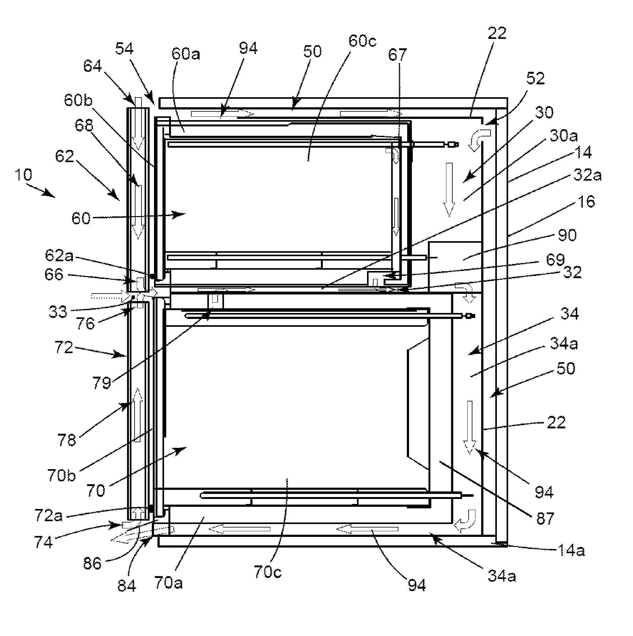
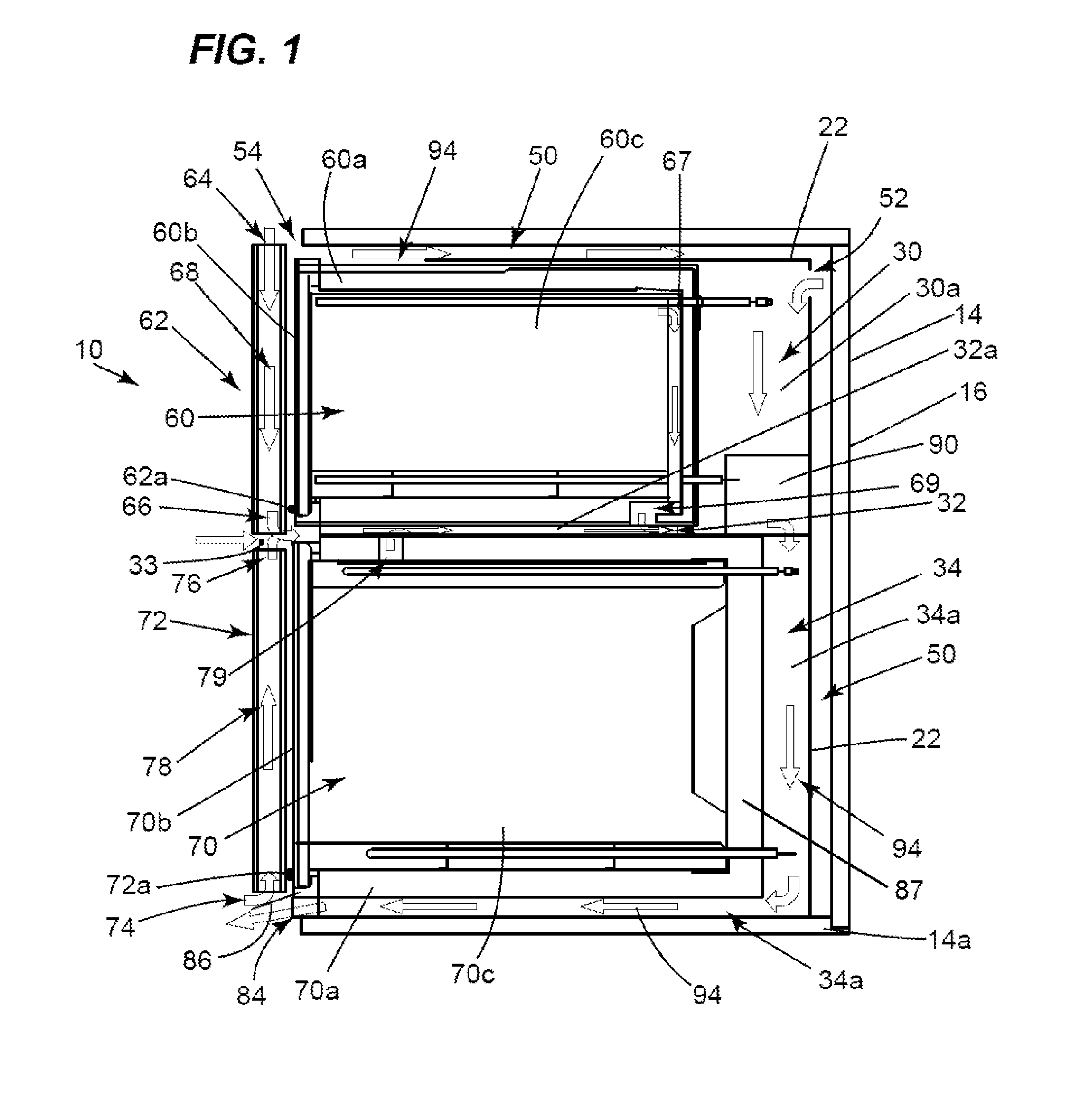
[0013]Referring to FIG. 1, an exemplary appliance such as a dual-cavity oven incorporating a preferred embodiment of a vacuum-based reverse airflow cooling system in accordance with the present invention is generally designated by reference numeral 10. In FIG. 1, the oven 10 is disposed in a recess defined by a wall section 14. The oven 10 sits on the bottom 14a of the wall section 14. The oven 10 includes a housing 22 that defines first and second cavities 30, 34 therein. Preferably there is a gap 50 between the top and back of the wall section 14 and the top and back of the housing 22. The gap 50 is in flow or fluid communication with ambient air (i.e., the outside of the dual-cavity oven) through an air inlet 54. The back of the housing 22 has an air inlet 52 through which the first cavity 30 is in flow or fluid communication with the gap 50.

[0014]An upper, first oven unit 60 is disposed or positioned in the first cavity 30. The first oven unit 60 includes a first oven chamber 60...


PUM


Abstract

An appliance includes a housing having an airflow channel communicating with outside of the appliance; a first chamber in the housing and having a first opening; a first door for selectively closing the first opening, the first door having a first airway communicating with the outside of the appliance; a second chamber in the housing and having a second opening; a second door for selectively closing the second opening, the second door having a second airway communicating with the outside of the appliance; and a fan in the airflow channel. The airflow channel includes a central segment disposed between the first and second chambers and communicating with the first and second airways. When activated, the fan causes ambient air to pass through the first and second airways before entering the central segment so that the first and second doors are cooled off by the ambient air.

Description

CROSS-REFERENCE TO RELATED APPLICATIONS[0001]This application relates to the commonly owned application entitled “Appliance with a Vacuum-Based Reverse Airflow Cooling System”, Ser. No. 12 / 209,280, filed concurrently.BACKGROUND OF THE INVENTION[0002]The present invention relates generally to an appliance. More particularly, the present invention relates to an appliance with a vacuum-based reverse airflow cooling system using one fan.[0003]Dual-cavity ovens typically draw in ambient or cooling air via intakes located above the upper oven cavity and at the top of the oven where the controls are situated. Each oven cavity includes a fan for cooling the respective oven unit independently of the other oven unit. The fans may blow the air down the back of the oven units. The exhaust air for this type of system is usually evacuated at locations between the upper and lower oven units and also below the lower oven unit on the front side of the oven.[0004]Typical duel-cavity oven designs limi...

Claims


Application Information

Patent Timeline
Patent Type & Authority Patents(United States)
IPC IPC(8): F24C15/32H05K7/00
CPCF24C15/006
Inventor ARMSTRONG, JAMESBARBER, PHILIP AMESBRONIAK, JAY ANDREWFROELICHER, STEVE B.LAUNDROCHE, KEVIN SCOTTMCGONAGLE, MICHAEL PAULWATKINS, DEREK LEE
Owner HAIER US APPLIANCE SOLUTIONS INC
Why Eureka
Try Eureka