Vibrotactile haptic feedback devices
a haptic feedback and vibrotactile technology, applied in repeater circuits, instruments, line-transmission details, etc., can solve the problems of severely restricting the force feedback effect, and the ability to change the natural frequency of a moving
- Summary
- Abstract
- Description
- Claims
- Application Information
AI Technical Summary
Problems solved by technology
Method used
Image
Examples
embodiment 100
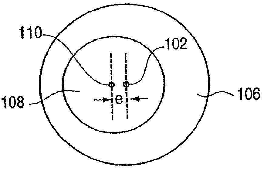
[0057]FIG. 3a is a top plan view of one implementation 100 using magnetic springs. Embodiment 100 provides a magnet 102 grounded to the device's housing 104 with a coil 106 wound around it. A yoke 108 is coupled to a magnet 110a one side and a magnet 110b on its other side, and holds the magnets 110 on each end of the fixed magnet 102. The magnets can be aligned approximately co-axially and can be oriented with north and south facings as shown. The yoke is rotatably coupled to a pivot 112, which is grounded (to the housing, for example), so that the yoke can rotate about an axis B. Current is flowed through the coil 106 from a current source, which can be used to add or subtract from (or cancel) the internal magnetic field between magnets 102 and 110 and which in turn influences the stiffness of the forces between yoke 108 and magnet 102, thereby adjusting the compliance of the suspension between yoke and housing. Current is flowed through the coil 106 as an oscillating (e.g. period...
embodiment 172
[0064]FIG. 6 is a schematic view of a different embodiment 172 of an actuator assembly which provides a variable flexibility between mass and housing. A grounded rotary actuator 173 rotates a lead screw 174. A clamp 175 is coupled to the lead screw 174 at a threaded bore 176 in the clamp so that the clam 175 moves along the lead screw as the screw is rotated. A cantilever 176 is grounded at one end, is threaded through rollers 177 or other clamp elements, and is coupled to a magnetic mass 178 at its other end. A coil 179 and core 181 are grounded and positioned adjacent to the mass 178. When a current is flowed through the coil 179, the magnetic force causes the mass 178 to move; driving current having a forcing function causes the mass 178 to move back and forth as shown by arrows 183, causing a vibration in the housing. This configuration allows independent control over frequency and magnitude of the vibrations when inputting different drive waveforms. The cantilever 176 is flexib...
embodiment 400
[0089]FIG. 14 is a schematic diagram of a solenoid embodiment 400 of an actuator assembly which provides linear oscillations and vibrations to the housing of an interface device. A core 402 made of iron or steel is positioned between a coil 404 wrapped around a cylindrical housing 406. A south pole magnet 408 is positioned on one side of the core 402, and a north pole magnet 410 is positioned on the other side of the core 402. A core end 412 is made of iron or steel and is positioned adjacent to the south pole magnet 408. Another north pole magnet 414 is positioned on the other side of the core end 412. The two north pole magnets 410 and 414 at the ends of the assembly act as non-linear springs which center the south pole magnet 408 within the coil 404.
[0090]The external magnetic field from the coil 404, caused by flowing current therethrough, is used to move the magnets 402 and 408 and core 402 linearly, as shown by arrow 416. By oscillating the current in the coil, these parts are...
PUM
 Abstract
Description
Claims
Application Information
 - R&D
- Intellectual Property
- Life Sciences
- Materials
- Tech Scout
- Unparalleled Data Quality
- Higher Quality Content
- 60% Fewer Hallucinations
Browse by: Latest US Patents, China's latest patents, Technical Efficacy Thesaurus, Application Domain, Technology Topic, Popular Technical Reports.
© 2025 PatSnap. All rights reserved.Legal|Privacy policy|Modern Slavery Act Transparency Statement|Sitemap|About US| Contact US: help@patsnap.com


