Panel clamp

a technology of clamping and panels, applied in the direction of bolts, locking fasteners, light support devices, etc., can solve the problems of difficult use of conventional clamps, two hands required for installation, and inability to have two free hands

Active Publication Date: 2012-05-22
THOMAS & BETTS INT INC
View PDF25 Cites 72 Cited by
  • Summary
  • Abstract
  • Description
  • Claims
  • Application Information

AI Technical Summary

Problems solved by technology

One drawback with such clamps is that installation requires two hands.
In many situations, the installer must install the clamp while in an awkward position and having two free hands is not always possible.
Therefore, using conventional clamps is often a difficult task.

Method used


Image

  • Panel clamp
  • Panel clamp
  • Panel clamp

Examples


Embodiment Construction

[0019]The following detailed description refers to the accompanying drawings. The same reference numbers in different drawings may identify the same or similar elements. Also, the following detailed description does not limit the invention.

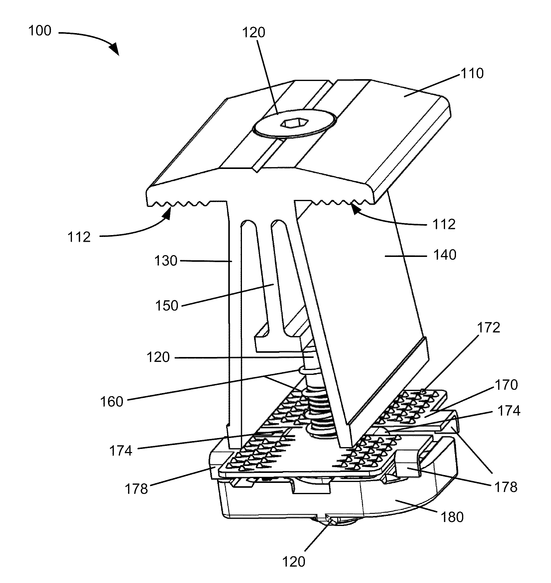
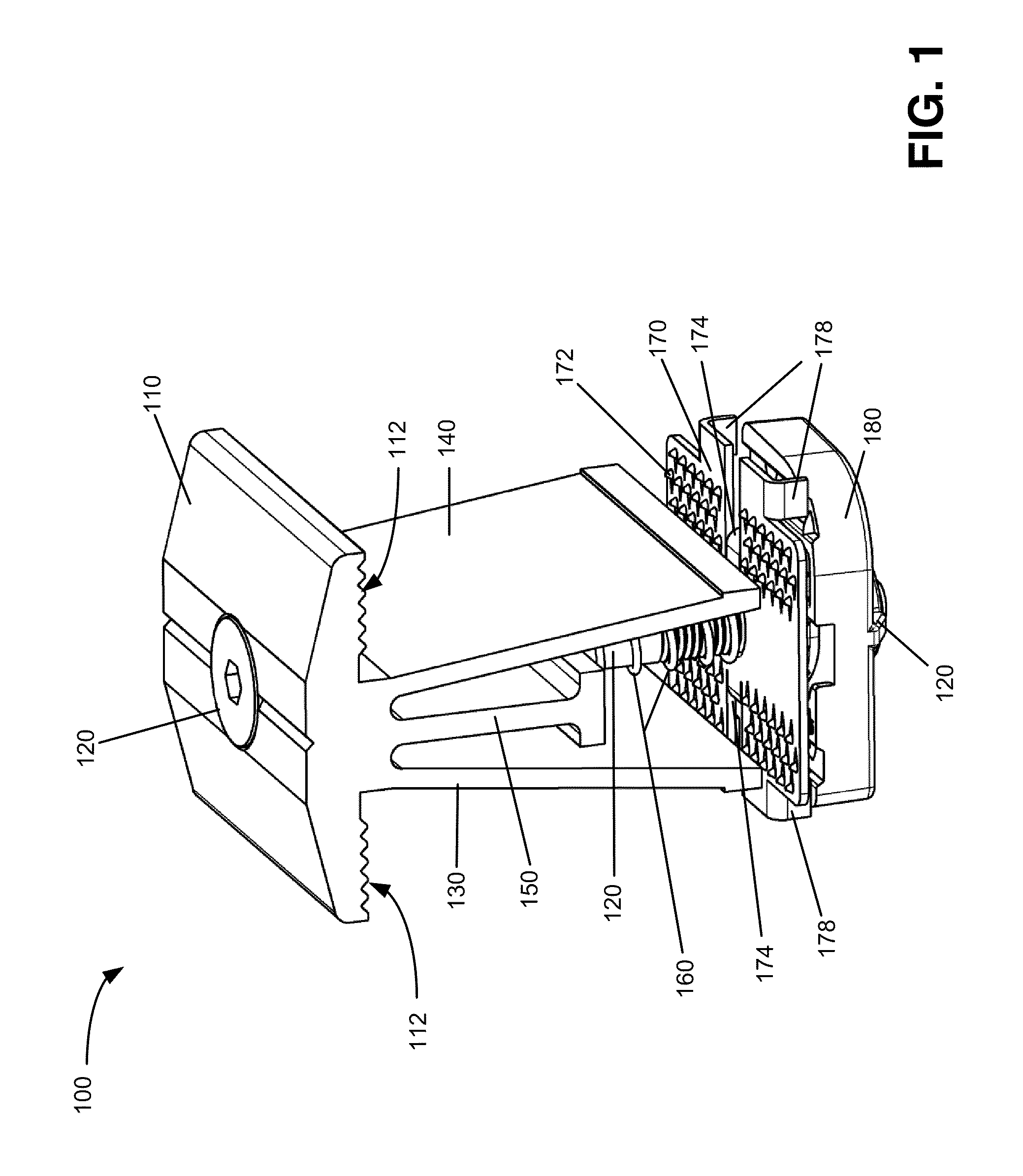
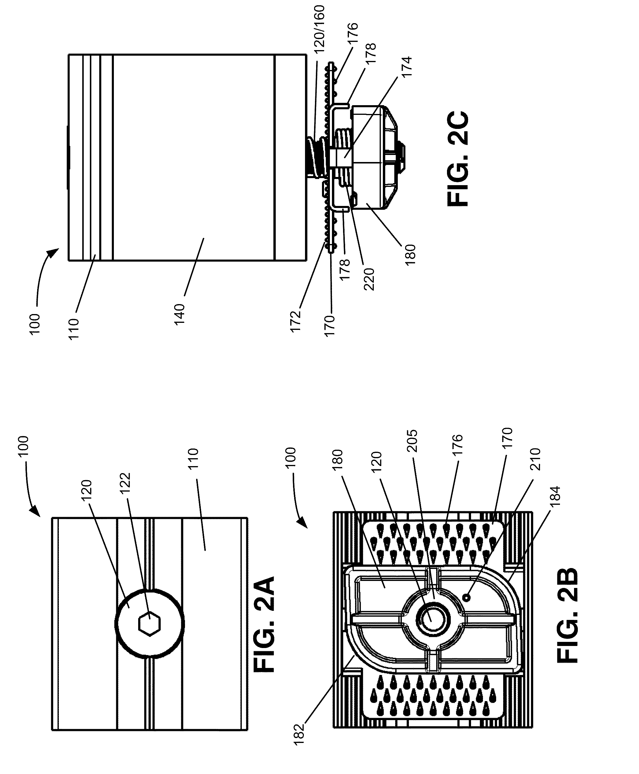
[0020]Embodiments described herein provide a clamp that that may be used in combination with a structural member, such as a strut channel, to clamp another member to the strut channel. In an exemplary implementation, the clamp may include a rotatable nut and a torsion spring. The rotatable nut may be held in place when the clamp is an initial position prior to connecting to the strut channel. When the clamp is to be connected to the strut channel, an installer may press a top portion of the clamp to release the rotatable nut. In response, the torsion spring causes the rotatable nut to automatically rotate into place within the strut channel. An installer may then tighten a clamp screw to secure the member / structure that is to be clamped to the str...


PUM


Abstract

A clamp includes a first member, a washer, a nut, a threaded bolt, a spring and a torsion spring. The first member may include side portions and have a first opening. The washer may include a second opening and at least one portion protruding in a downward direction from an upper surface of the washer. The nut may have an upper surface, a lower surface and a threaded opening. The threaded bolt may be disposed through the first opening, the second opening and the threaded opening. The spring may be located between a portion of the first member and the washer. The torsion spring may be located between the washer and the nut, where the torsion spring causes the nut to rotate when force is applied to an upper part of the first member.

Description

BACKGROUND INFORMATION[0001]Traditional clamps often include spring nuts that provide compression at a lower portion of the nut to hold the clamp to another structure, such as a strut. One drawback with such clamps is that installation requires two hands. That is, one hand is used to depress the entire assembly, while the other hand rotates the spring nut to the proper position. In many situations, the installer must install the clamp while in an awkward position and having two free hands is not always possible. Therefore, using conventional clamps is often a difficult task.BRIEF DESCRIPTION OF THE DRAWINGS[0002]FIG. 1 is an isometric view of a clamp consistent with an exemplary implementation;[0003]FIGS. 2A, 2B and 2C are top, bottom and side views, respectively, of the clamp of FIG. 1 according to an exemplary implementation;[0004]FIGS. 3A and 3B are a side view and a sectional view, respectively, of the clamp of FIG. 1;[0005]FIGS. 4A and 4B are an isometric view and side view, re...

Claims


Application Information

Patent Timeline
Patent Type & Authority Patents(United States)
IPC IPC(8): A47G29/02
CPCF24J2/5258Y10T24/44265Y10T24/44017Y02E10/47F24S25/636
Inventor MAGNO, JR., JOEY D.JOLLY, ROBERT K.COLE, ANDREW C.DINH, CONG T.
Owner THOMAS & BETTS INT INC
Why Eureka
Try Eureka